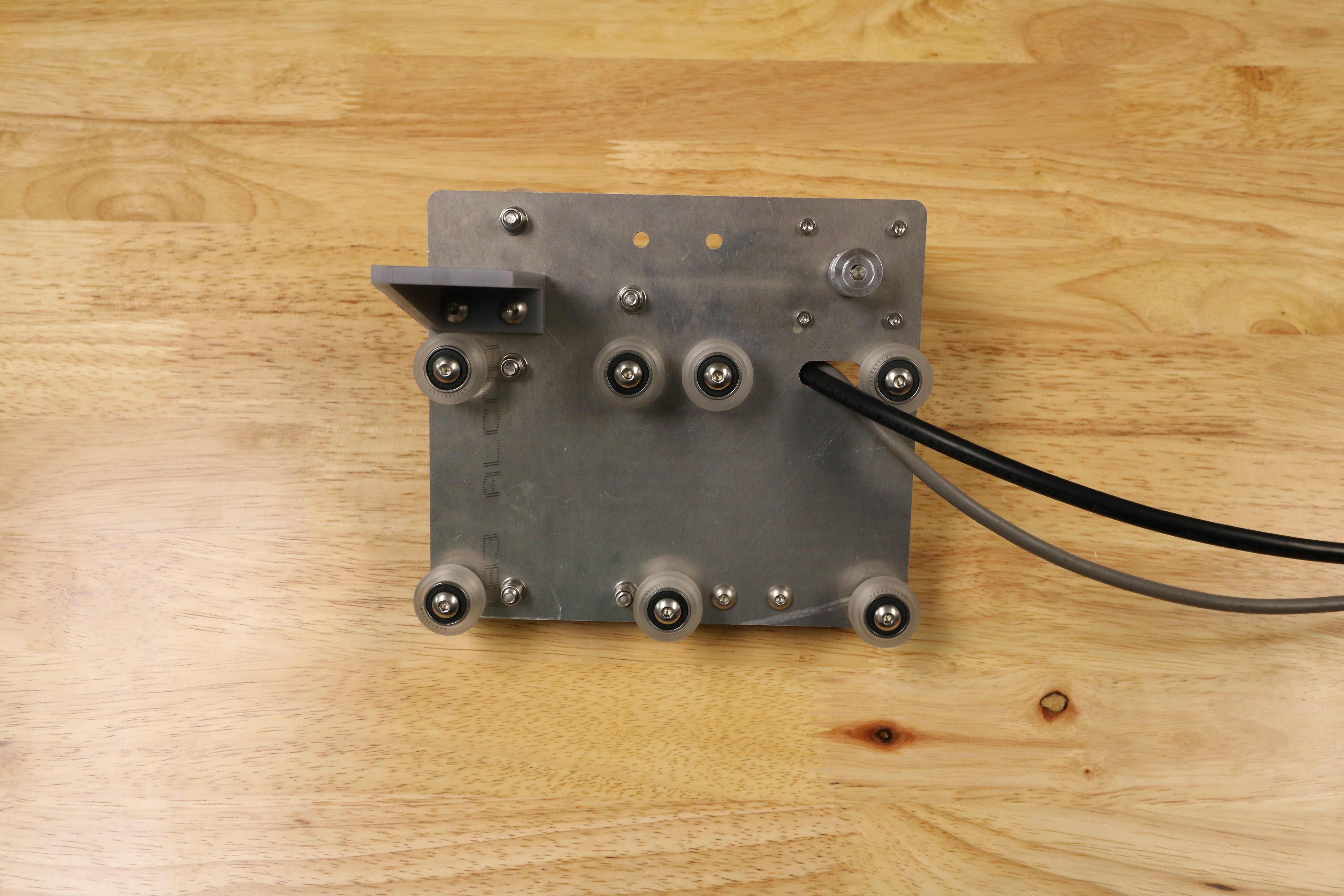
Cross-Slide Assembly
45 minutes
This is the estimated time it will take to assemble the Cross-Slide.
Step 1: Add the Gantry V-Wheels
Using M5 x 30mm screws, M5 washers, and M5 locknuts, attach four V-wheels with normal 6mm spacers to the holes shown with normal spacers.
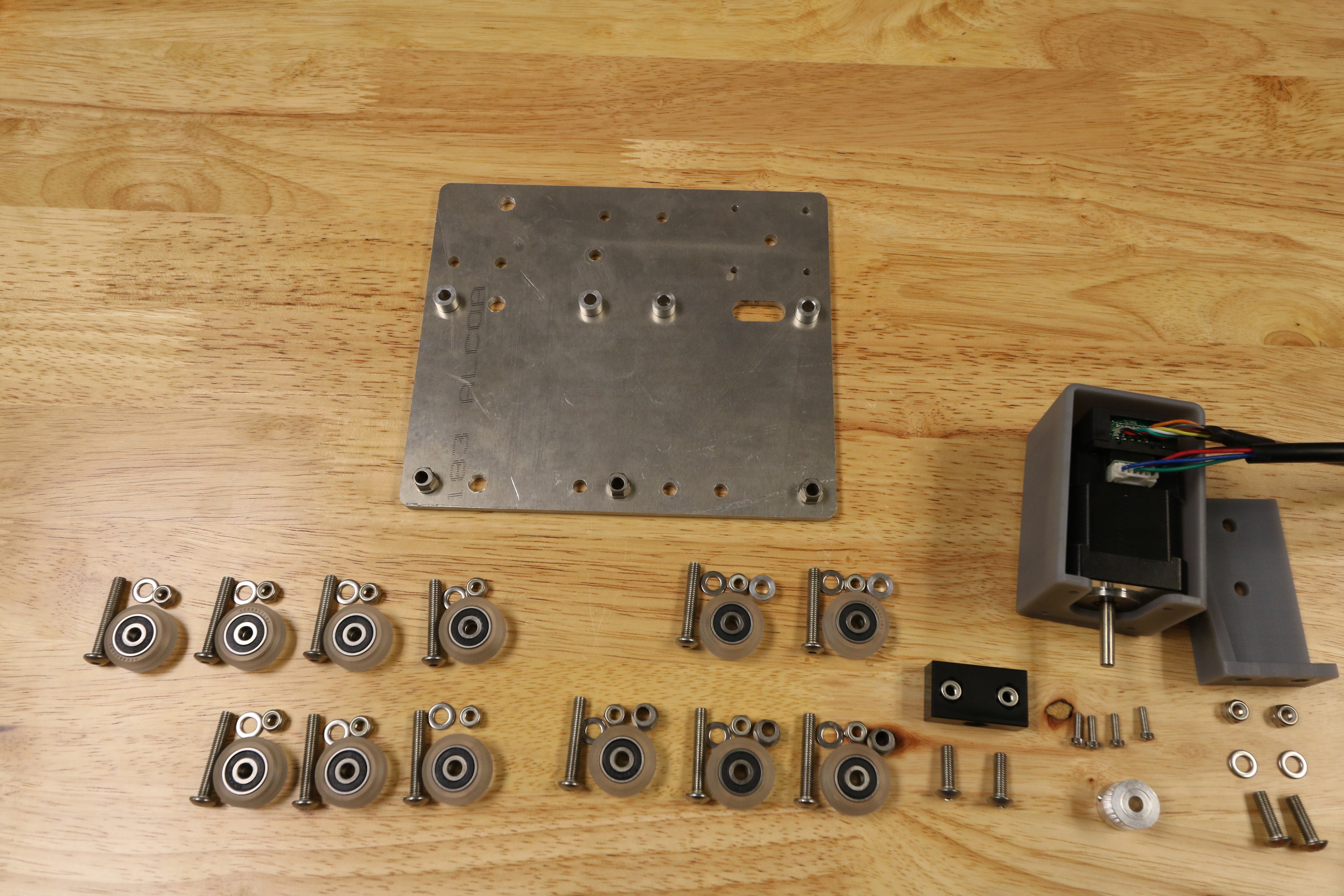

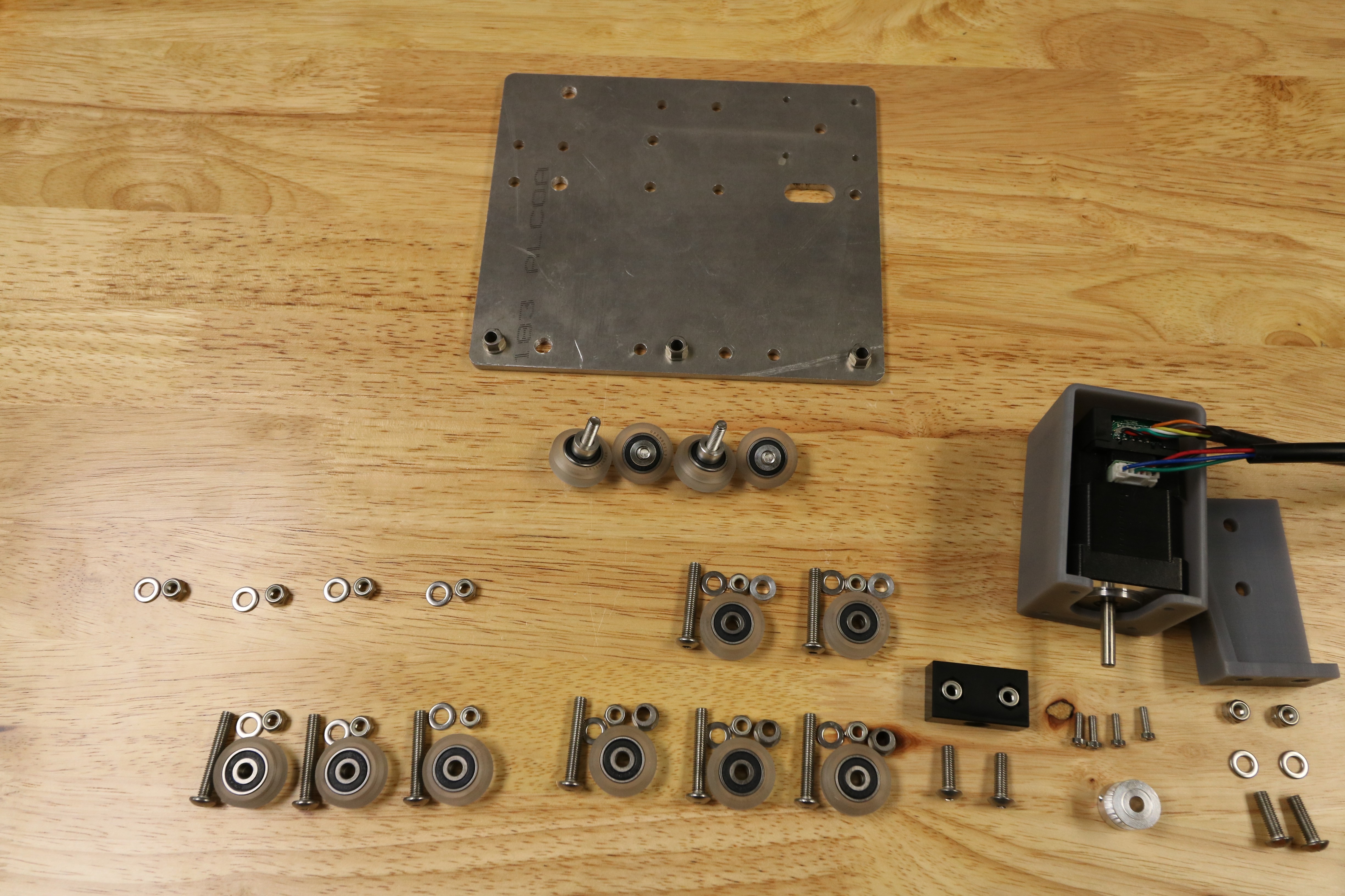
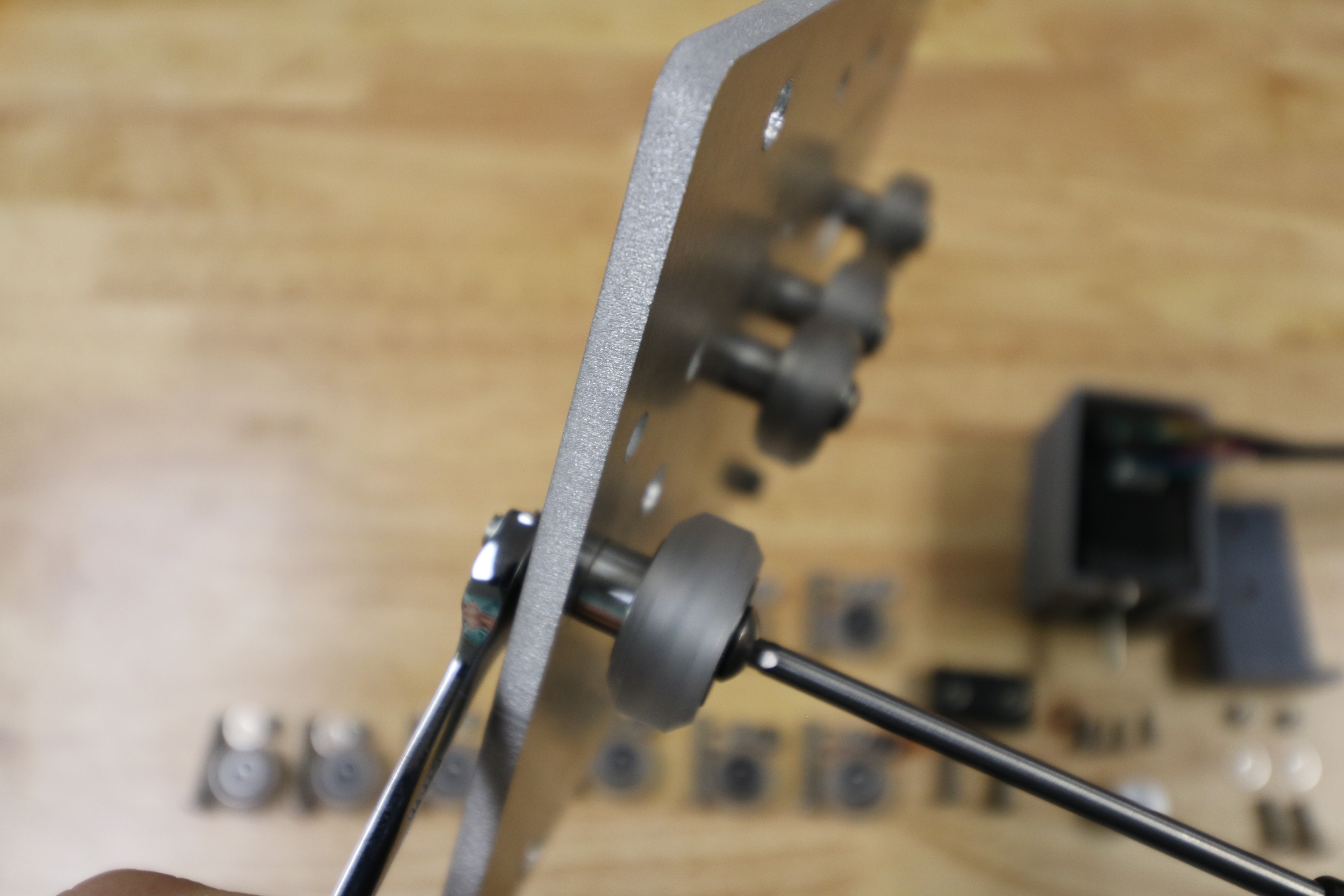
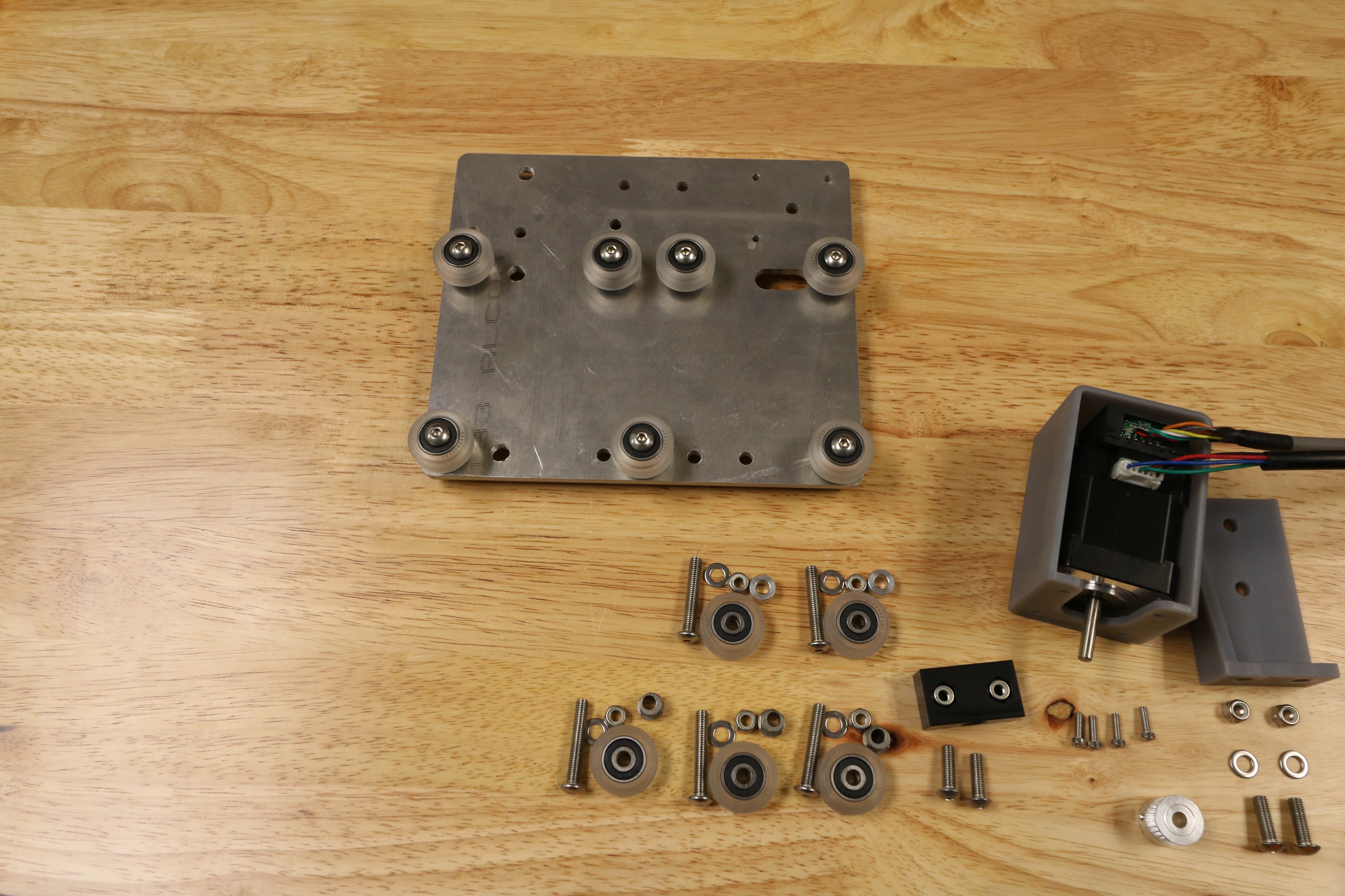
Add three V-wheels with eccentric 6mm spacers to the holes shown with eccentric spacers.
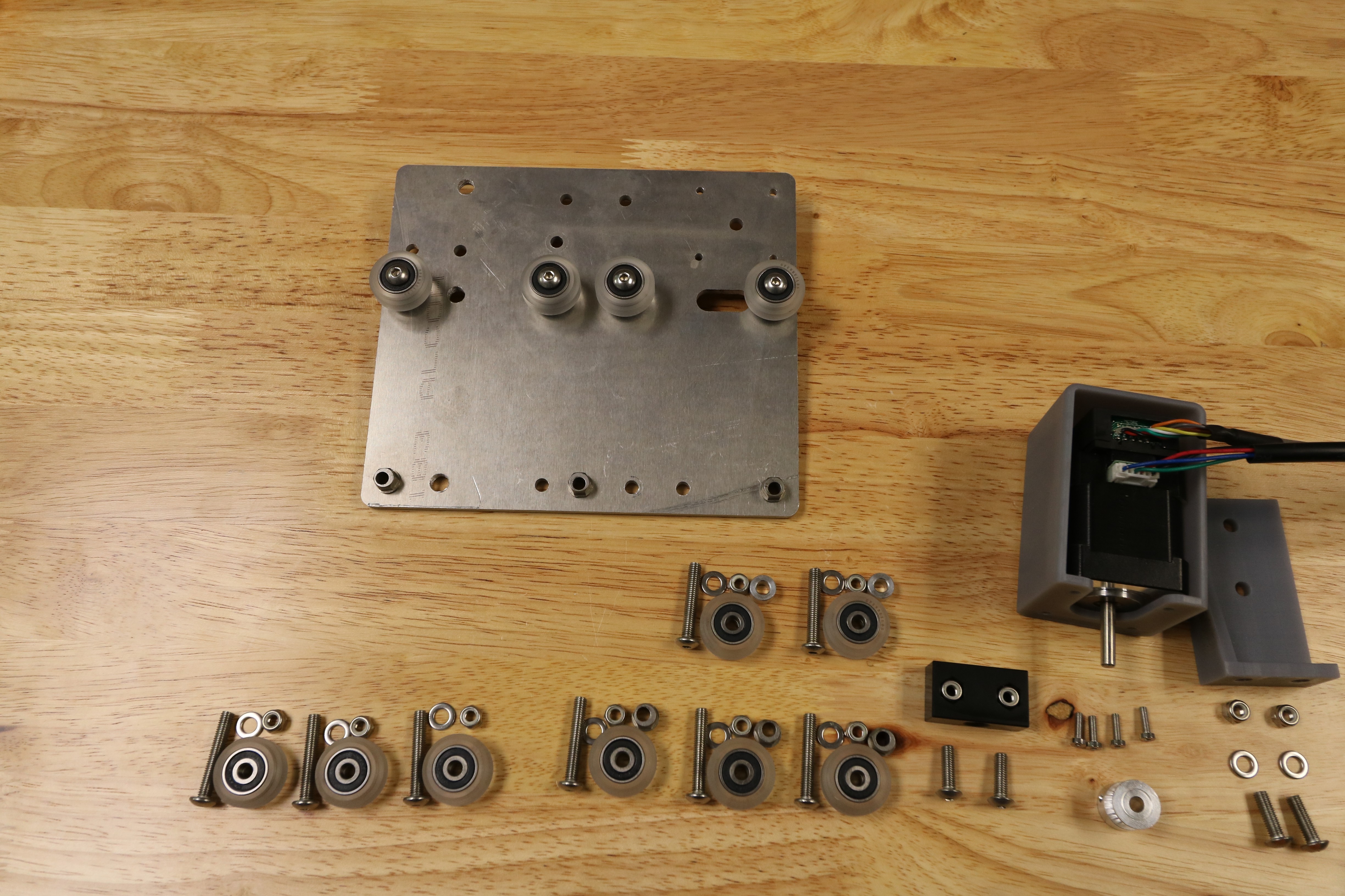

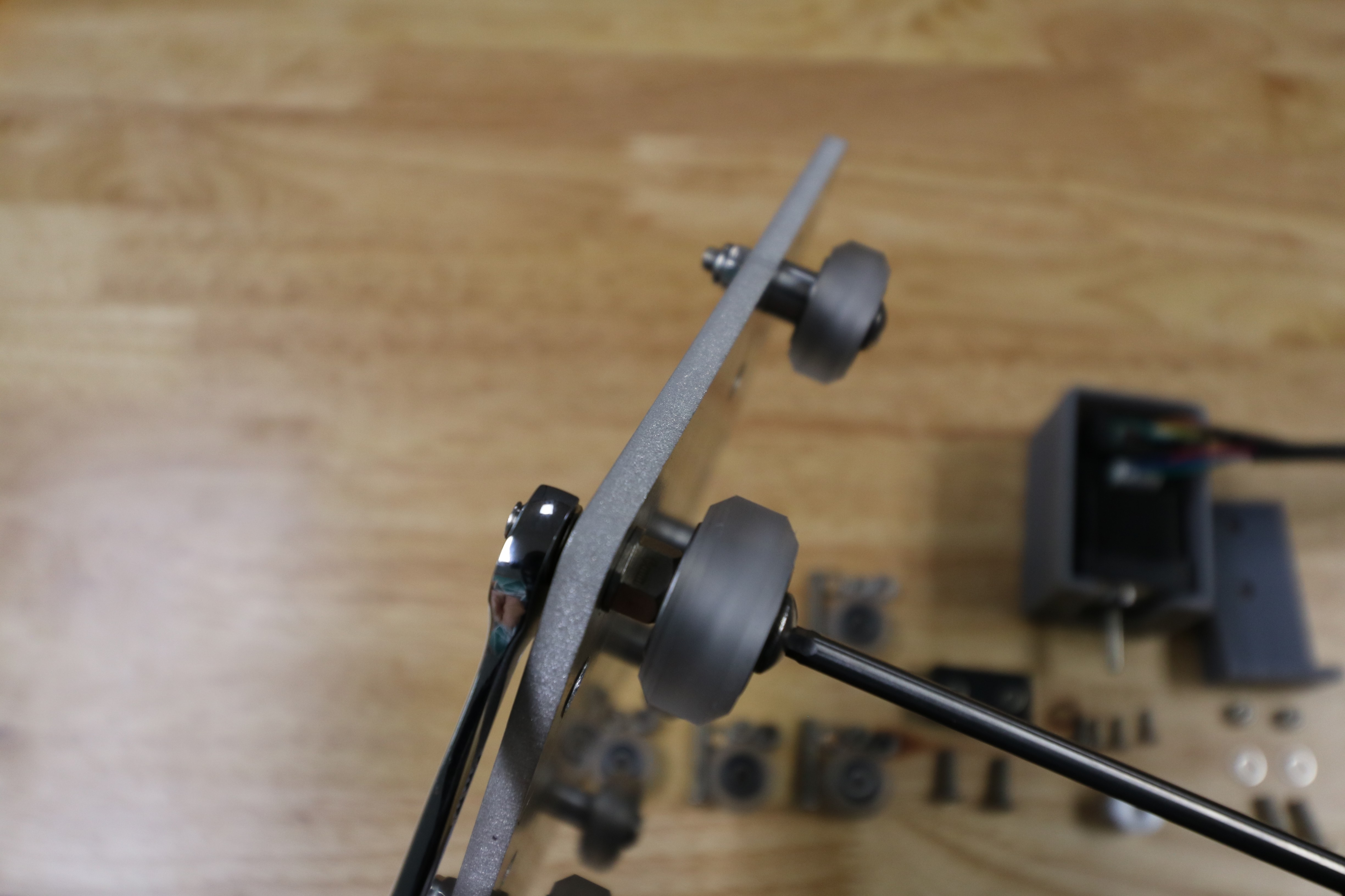
Cross-slide gantry V-wheels are now attached.
Step 2: Add the Z-Axis V-Wheels
Flip the cross-slide over so that all of the components you have added so far are facing away from you.
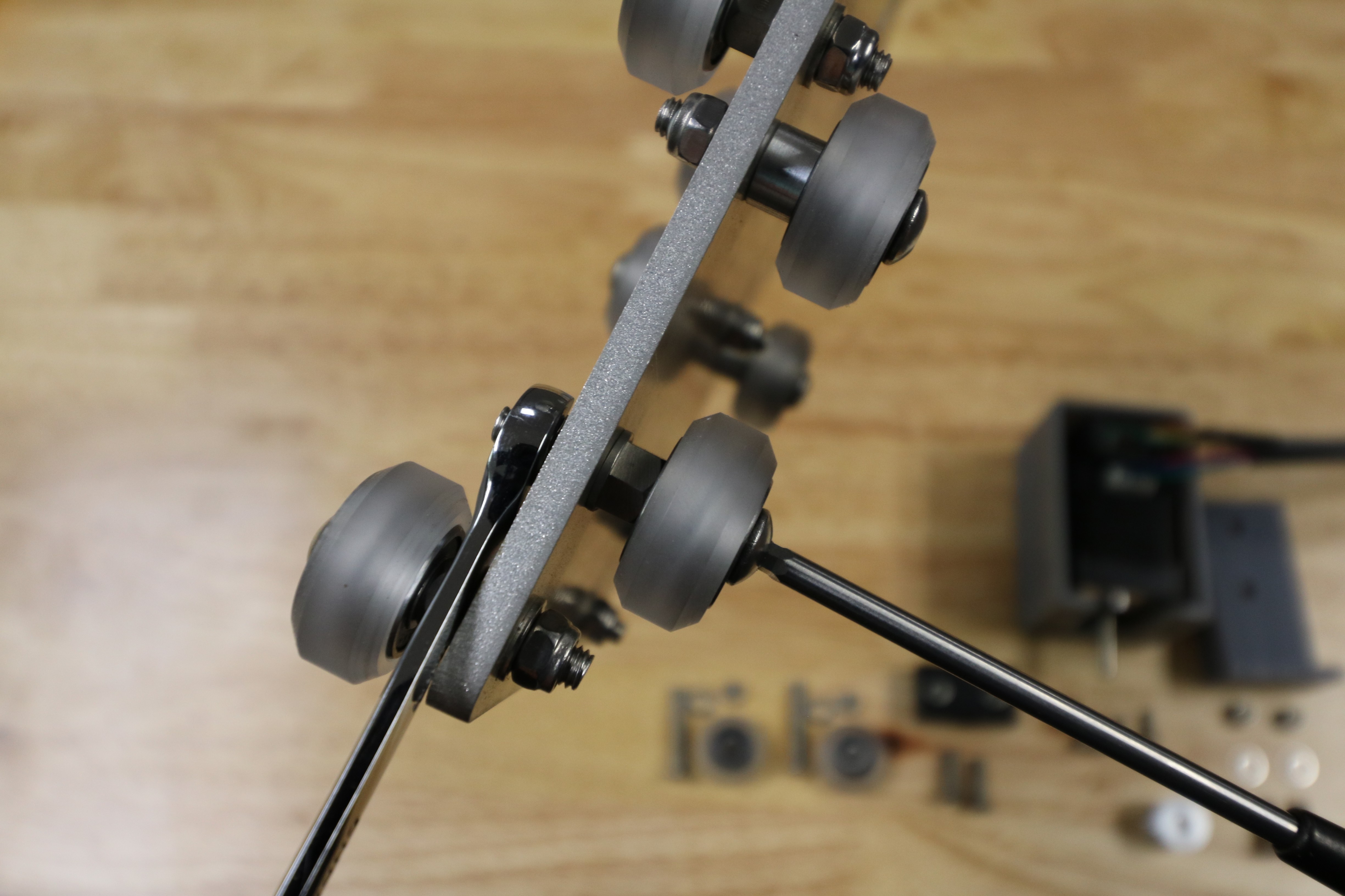
Add V-wheels with eccentric 6mm spacers to the holes shown. The V-wheels should be secured with an M5 washer and an M5 locknut on the other side.
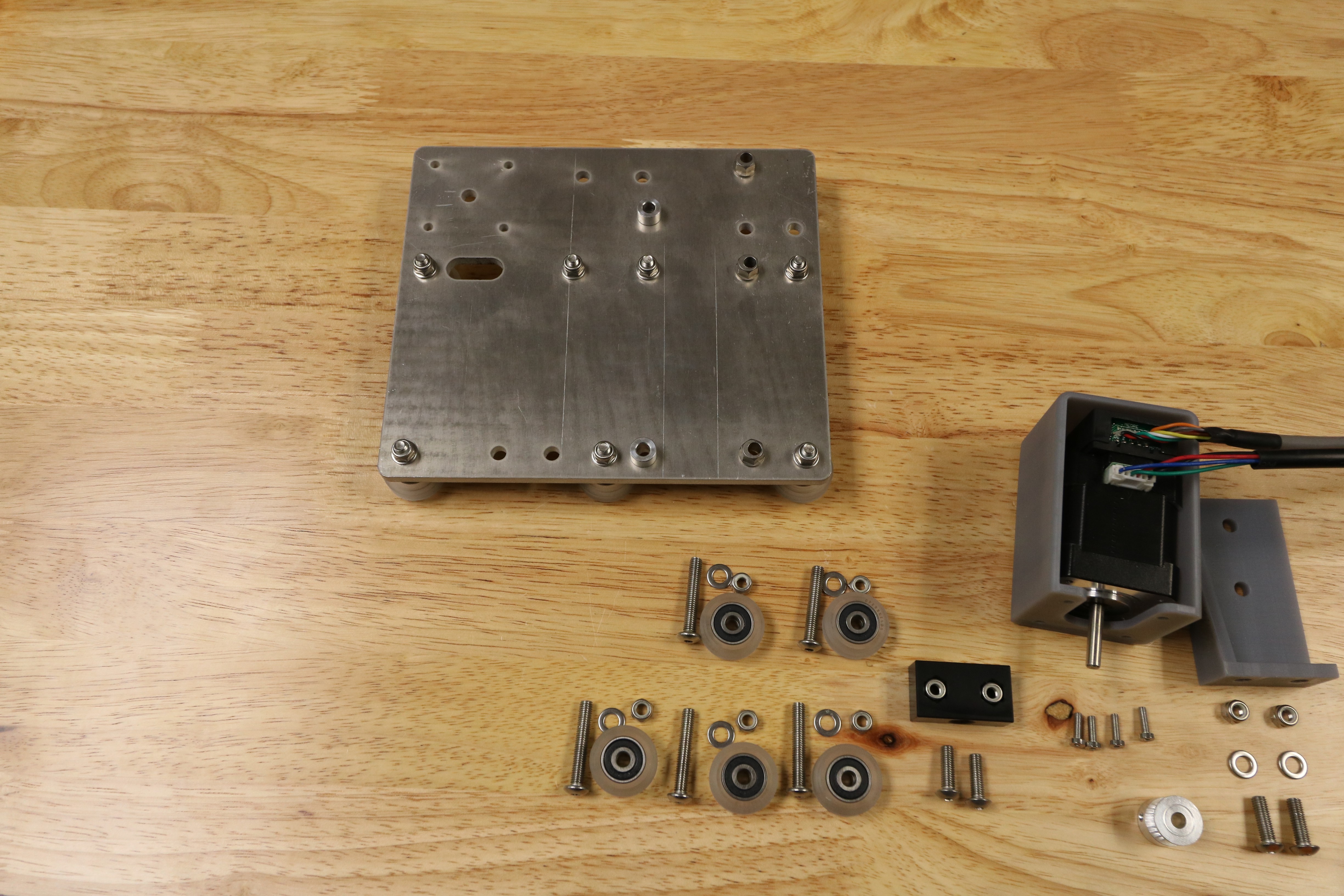
Using M5 x 30mm screws, attach two V-wheels with normal 6mm spacers to the holes shown above with normal spacers. Secure these wheels with an M5 washer and an M5 locknut on the other side of the plate.
Step 3: Attach the Delrin Leadscrew Block
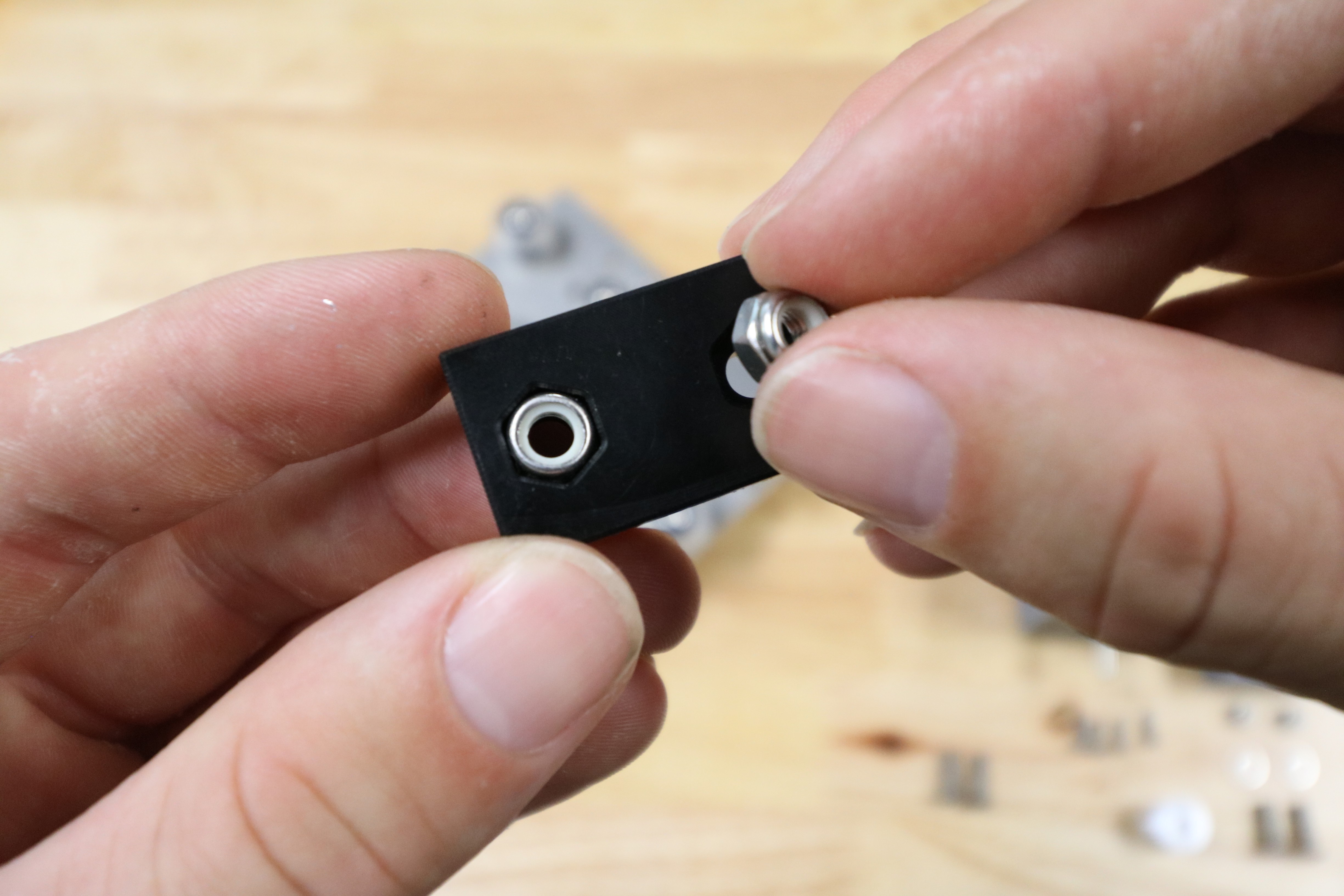
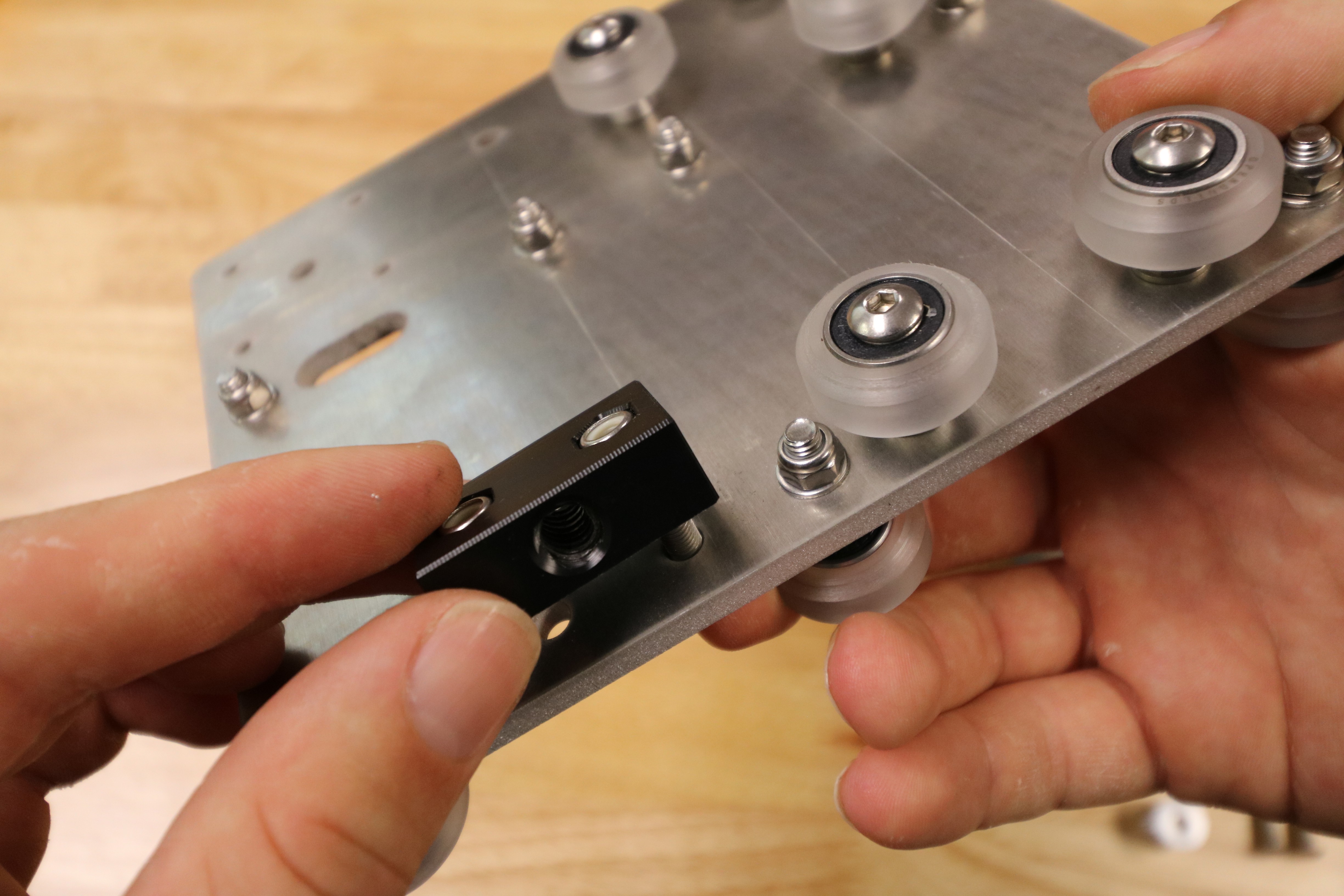
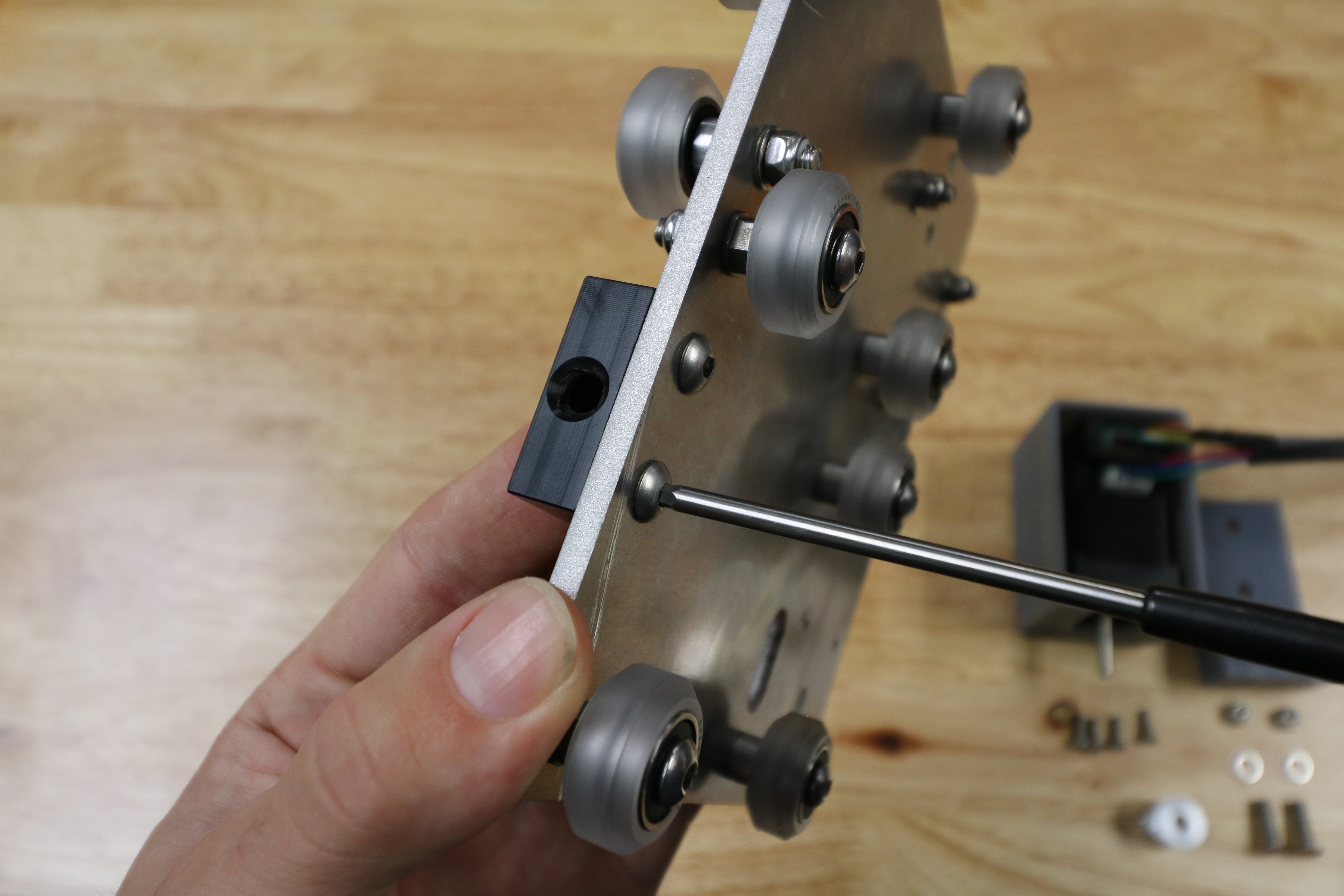
Use two M5 x 16mm screws and two M5 locknuts to attach the delrin leadscrew block to the cross-slide plate.
Plate orientation is key
Its pretty easy to orient your cross-slide plate wrong and attach a bunch of components to it facing the wrong direction. Take your time to study the photos in this step to ensure you attach things on the correct side of the plate the first time.

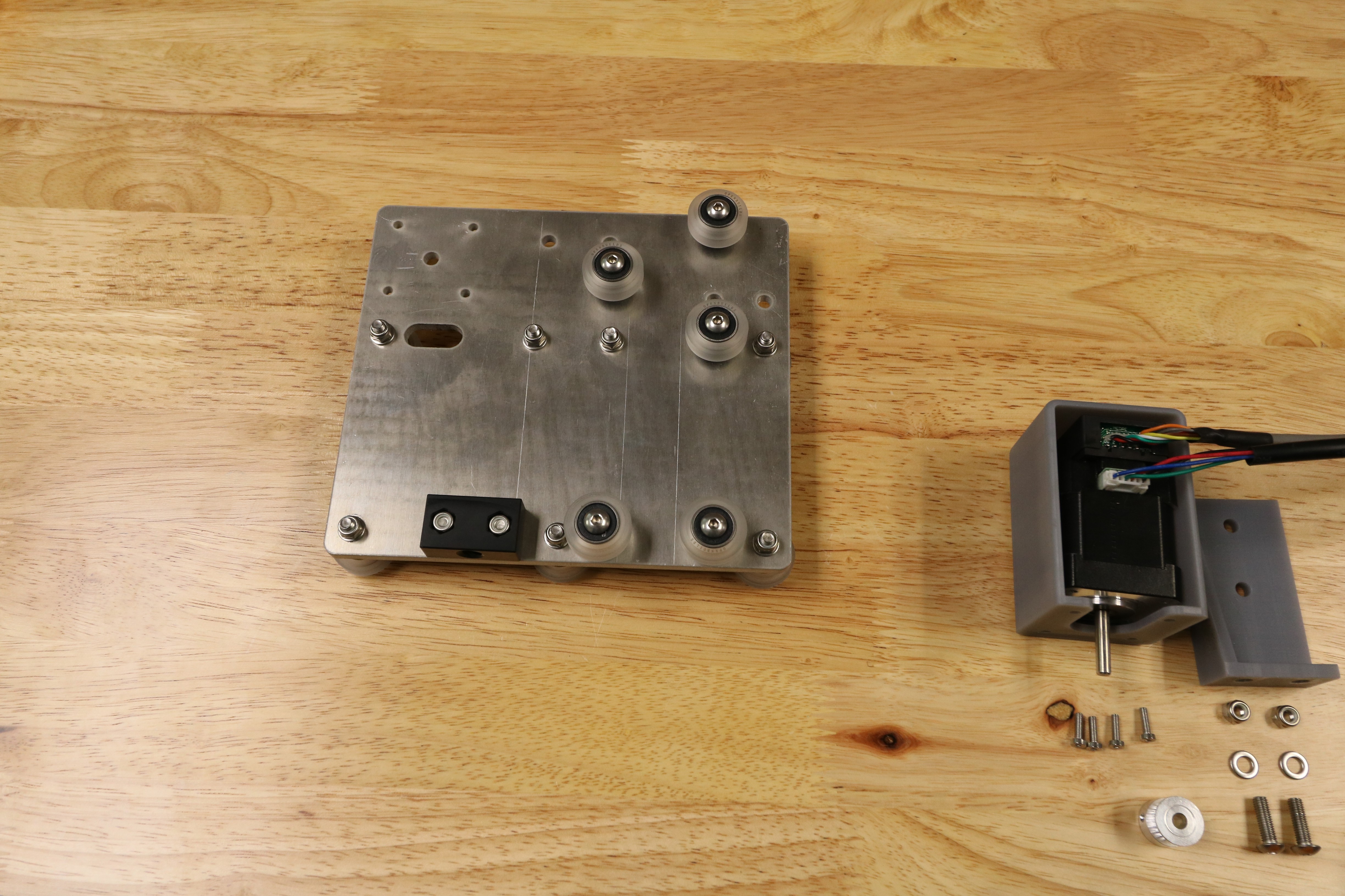
Step 4: Attach the Stepper Motor
Feed the motor and encoder cables through the wide slot on the cross-slide plate. The motor should be on the side opposite the seven gantry main beam V-wheels.
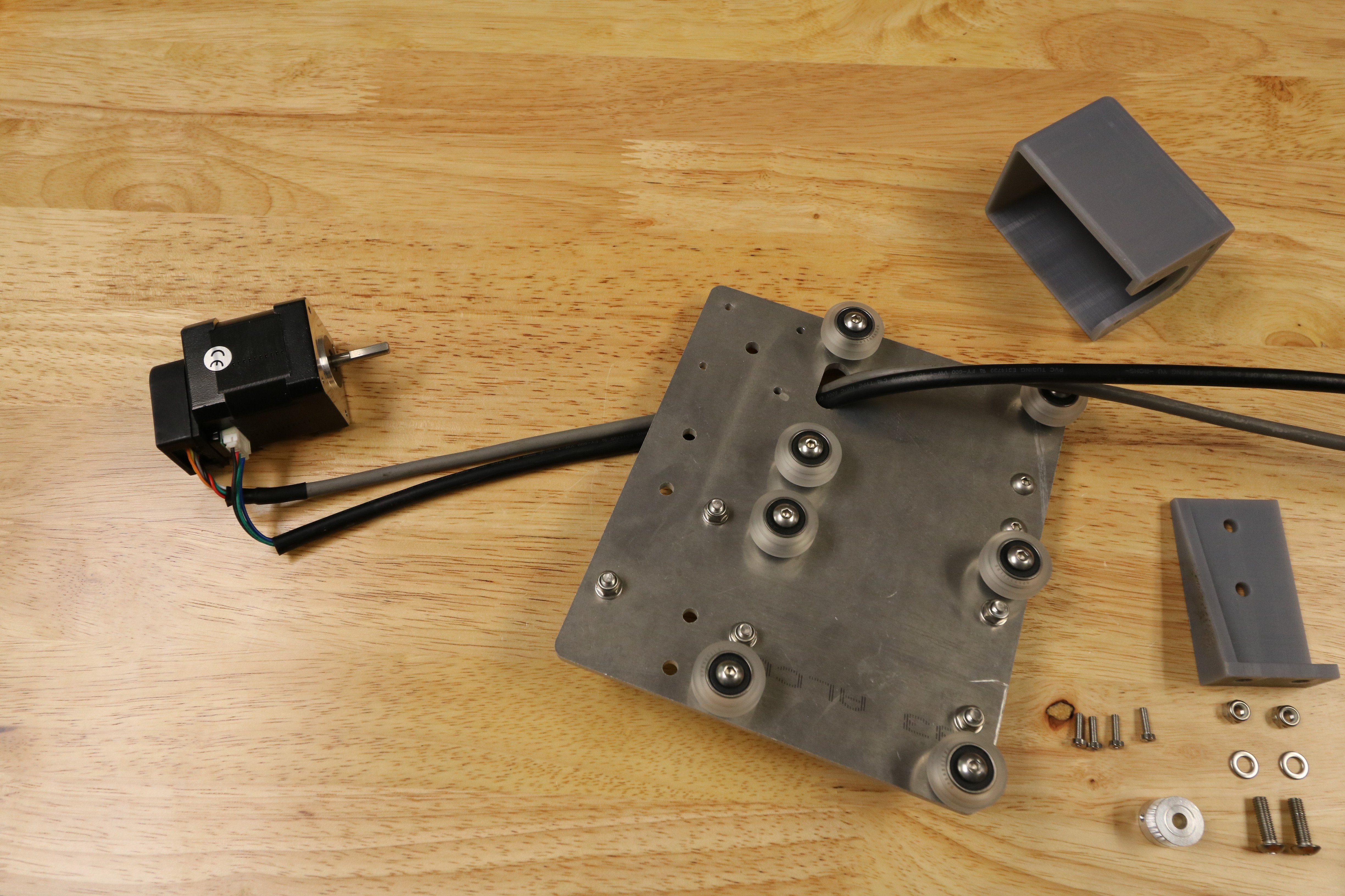
Insert the motor and encoder into the horizontal motor housing.
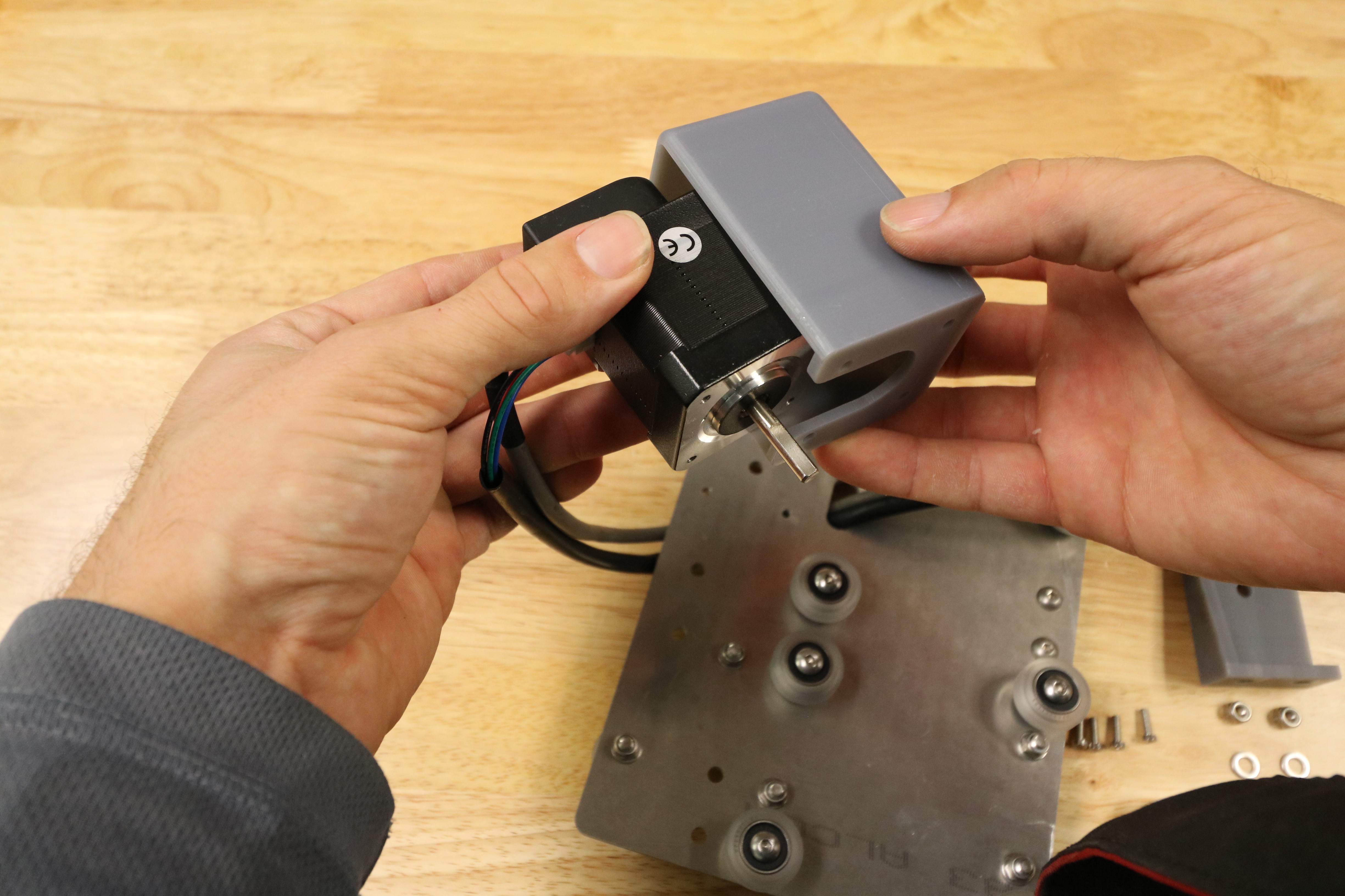
Use four M3x10mm screws to attach the stepper motor and motor housing to the cross-slide plate. Make sure the motor and housing are on the same side of the cross-slide plate as the delrin leadscrew block, and that the motor’s wiring and the motor housing’s open side is facing down towards the delrin leadscrew block.
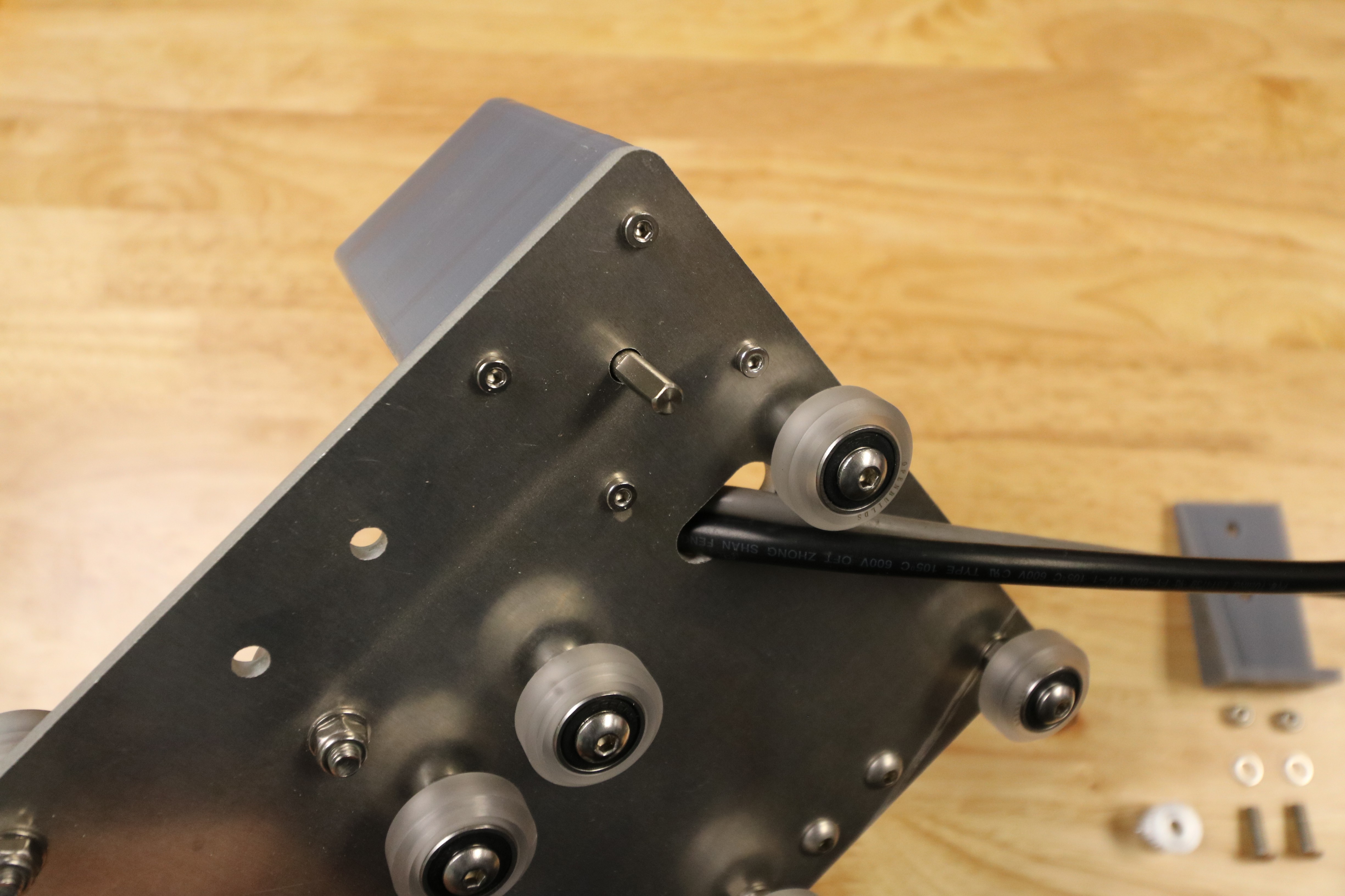
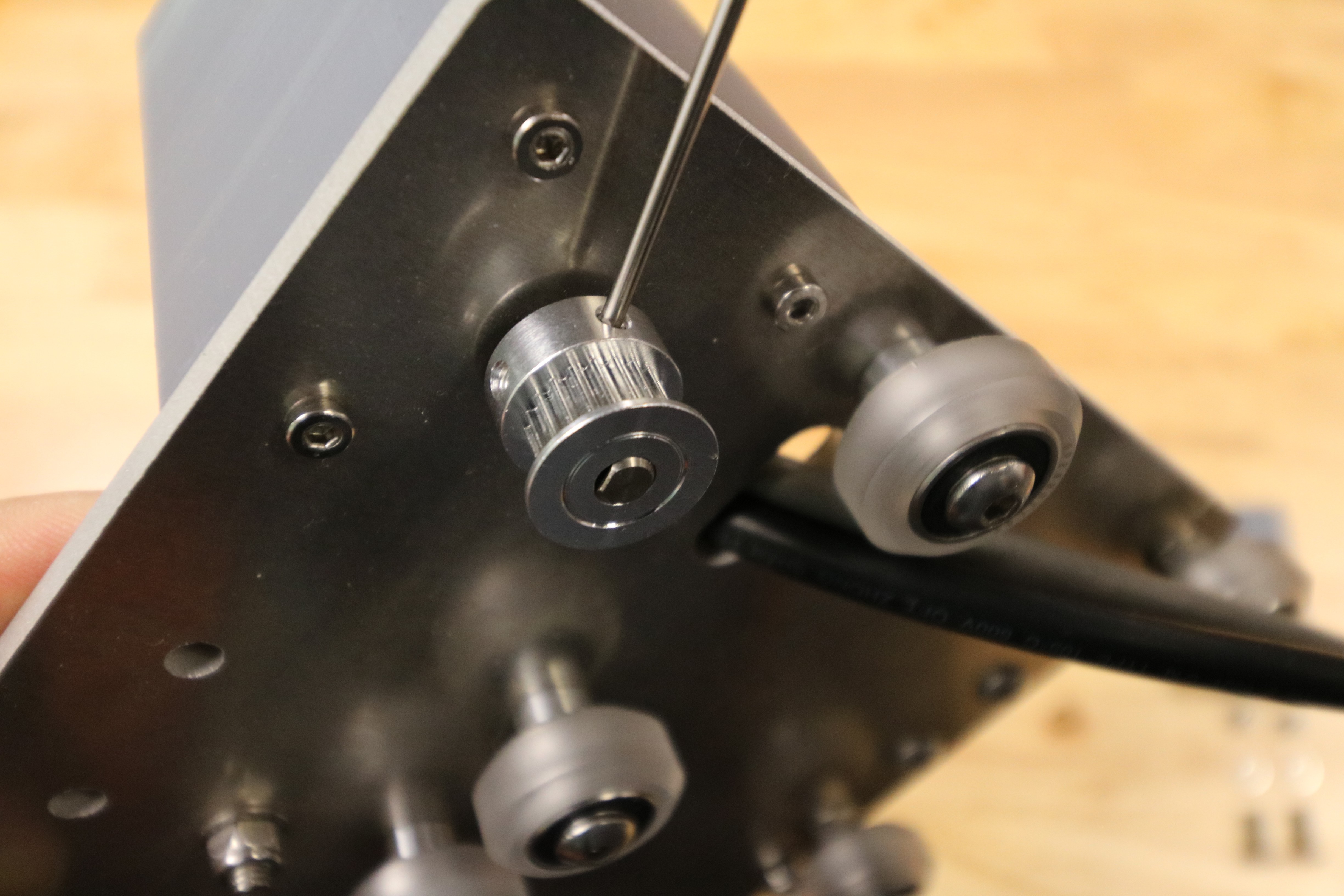
Slide a GT2 pulley onto the stepper motor shaft. Make sure that one of the setscrews is lined up with the flat spot of the motor shaft and then tighten the setscrews with the 2mm driver.
Step 5: Add the Cable Carrier Mounting Bracket
Use two M5 x 16mm screws, M5 washers, and M5 locknuts to secure the 3D printed cable carrier mounting bracket to the cross-slide plate. The bracket should be on the opposite side of the plate as the motor.
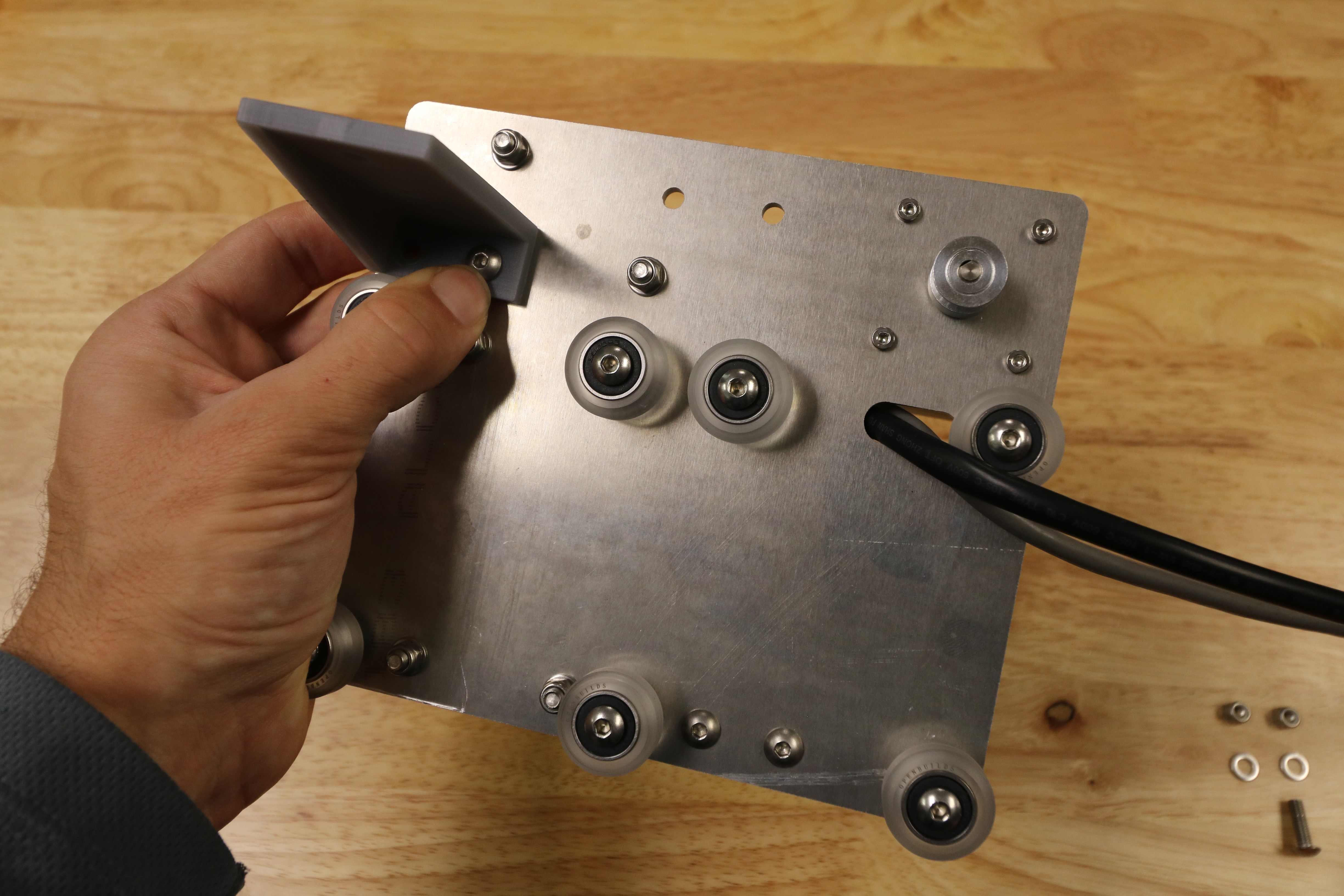
Congrats!
You’re now finished assembling the cross-slide.
