Attach the Drivetrain
Step 1: Attach the gantry motor
For this step you will need:
- One NEMA 17 stepper motor and rotary encoder
- One horizontal motor housing
- The gantry motor mount plate
- Four M3 x 16mm screws
- Three M5 x 10mm screws
- Three M5 tee nuts
- The 2mm and 3mm hex drivers
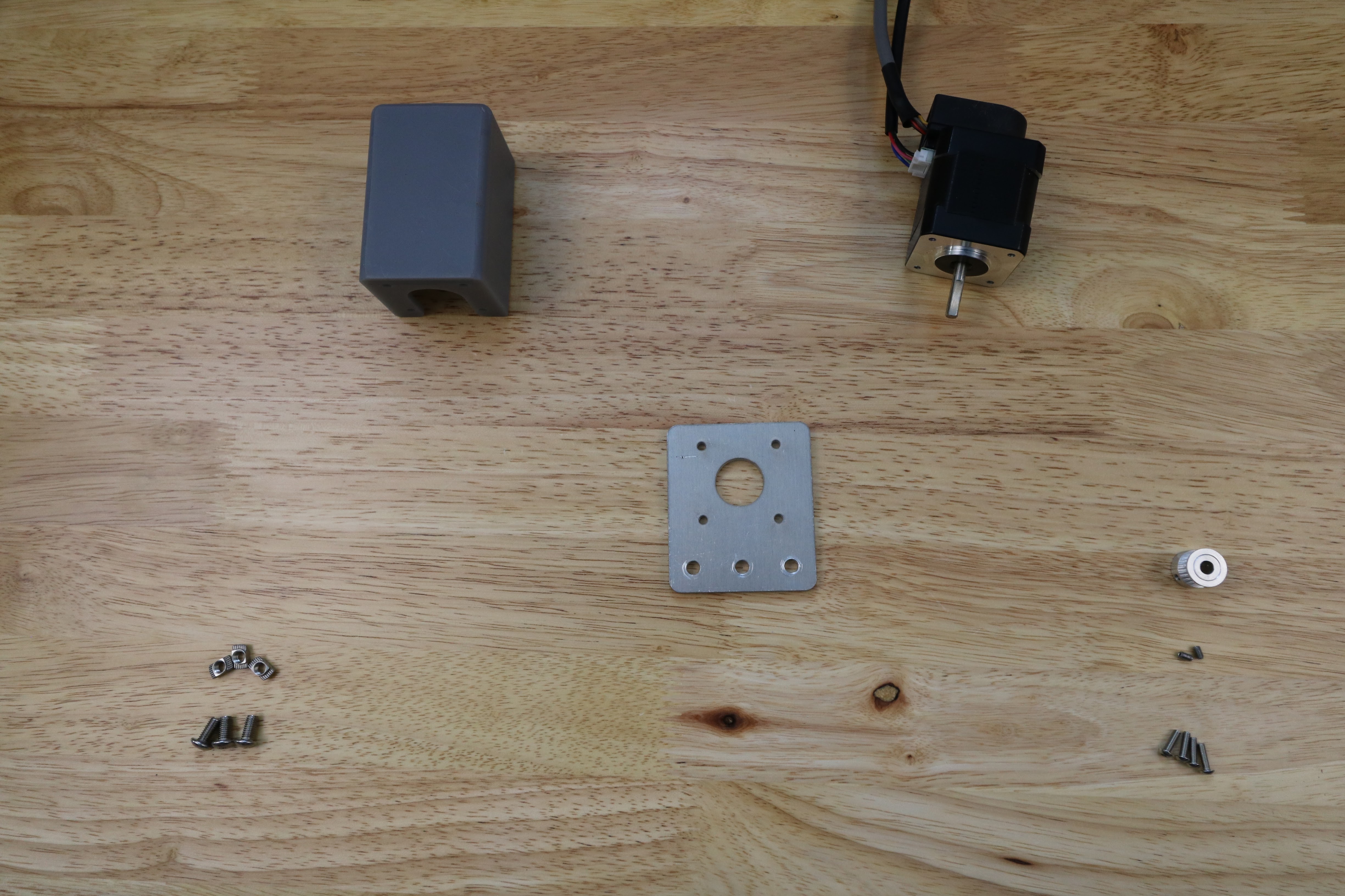
Slide the motor into the motor housing, ensuring that the shaft of the motor is coming out of the housing and that the motor and encoder’s wires are facing down through the open bottom of the housing.
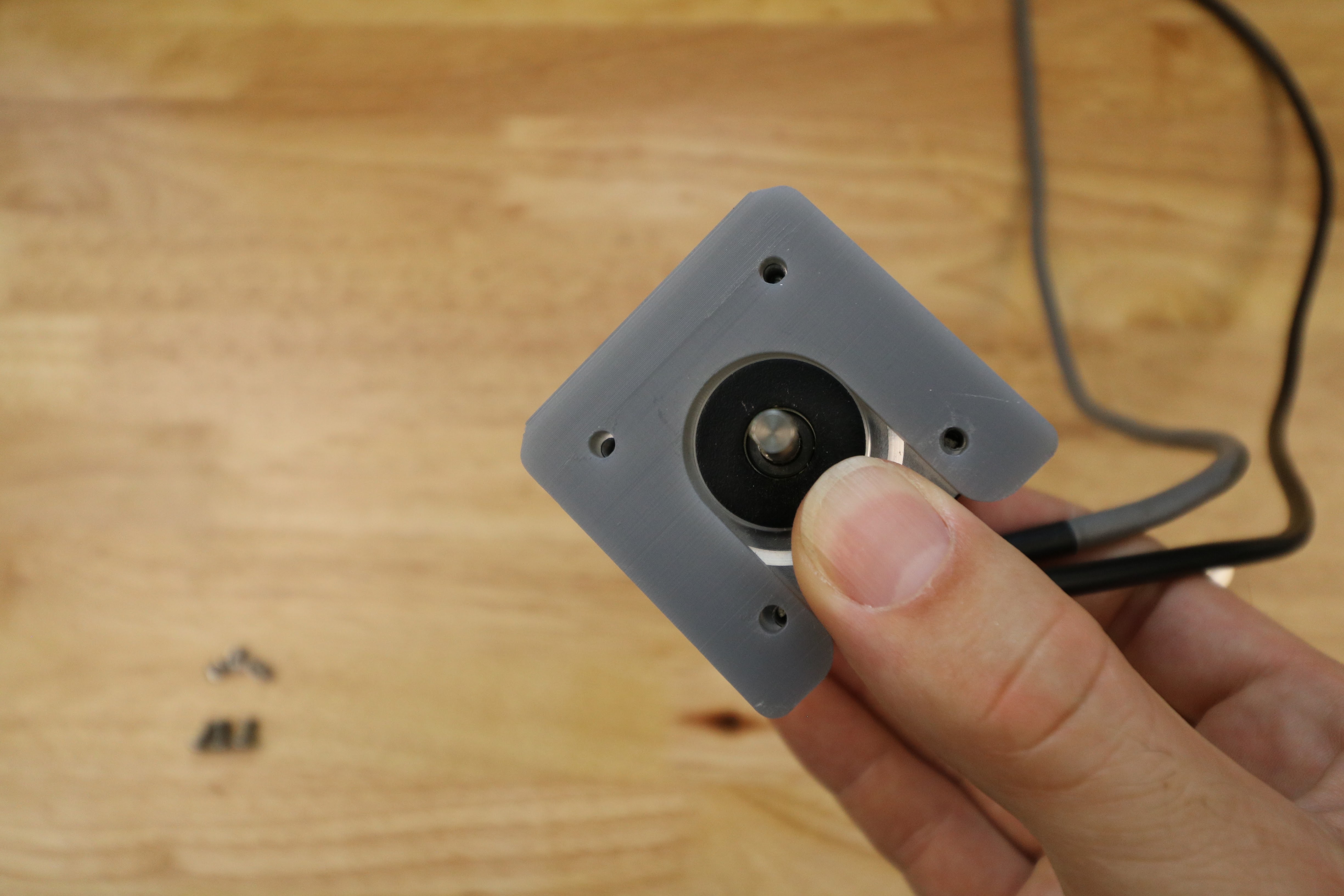
Slide the gantry motor mount plate onto the motor’s shaft and fit it flush against the motor housing. The M5 mounting holes of the plate should be facing the same direction as the motor’s wiring.
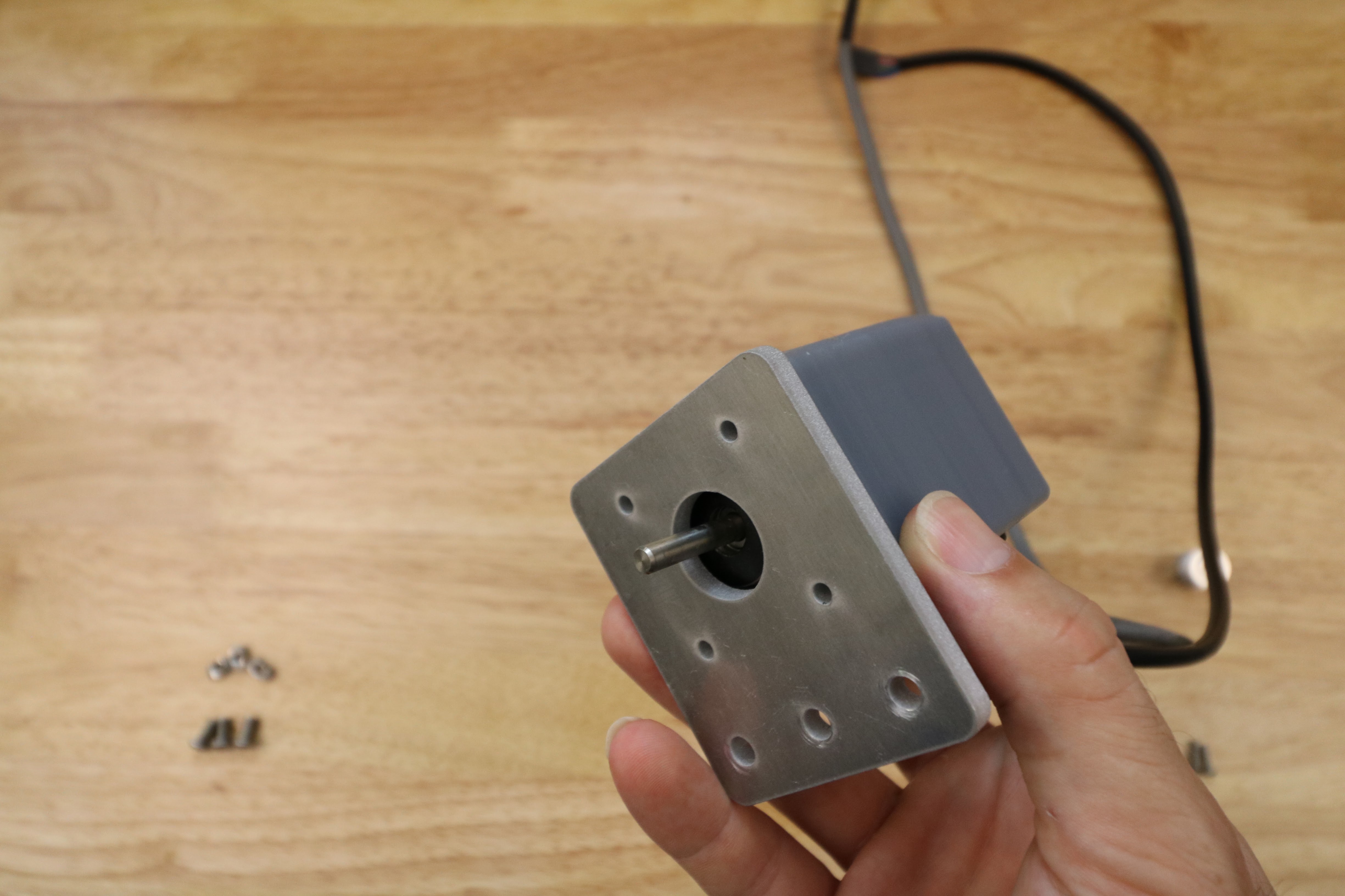
Then use the 2mm hex driver to and four M3 x 16mm screws to attach the motor mount plate and motor housing to the motor.
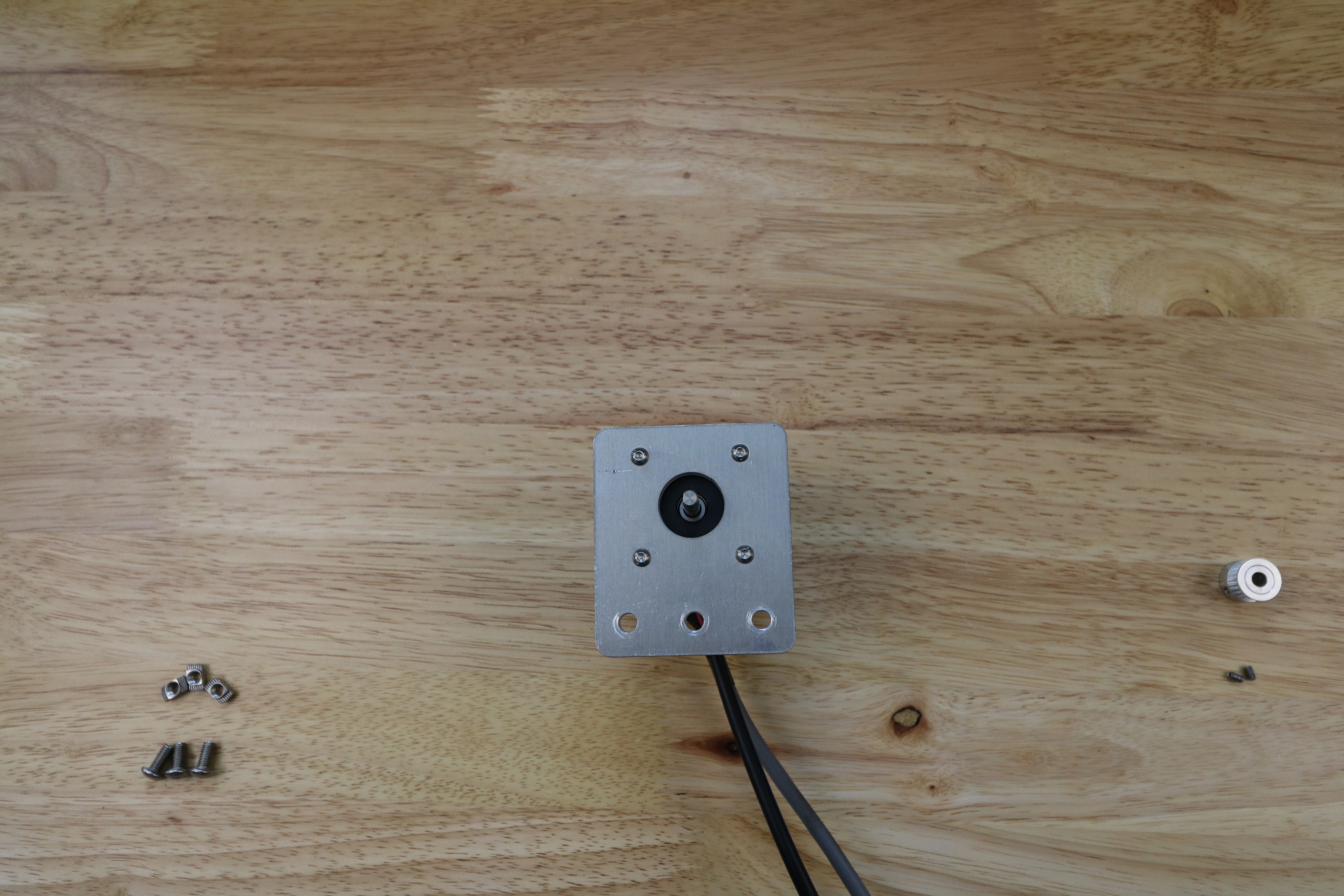
Slide a GT2 pulley onto the motor and tighten it using the two M3 setscrews and the 1.5mm hex driver.
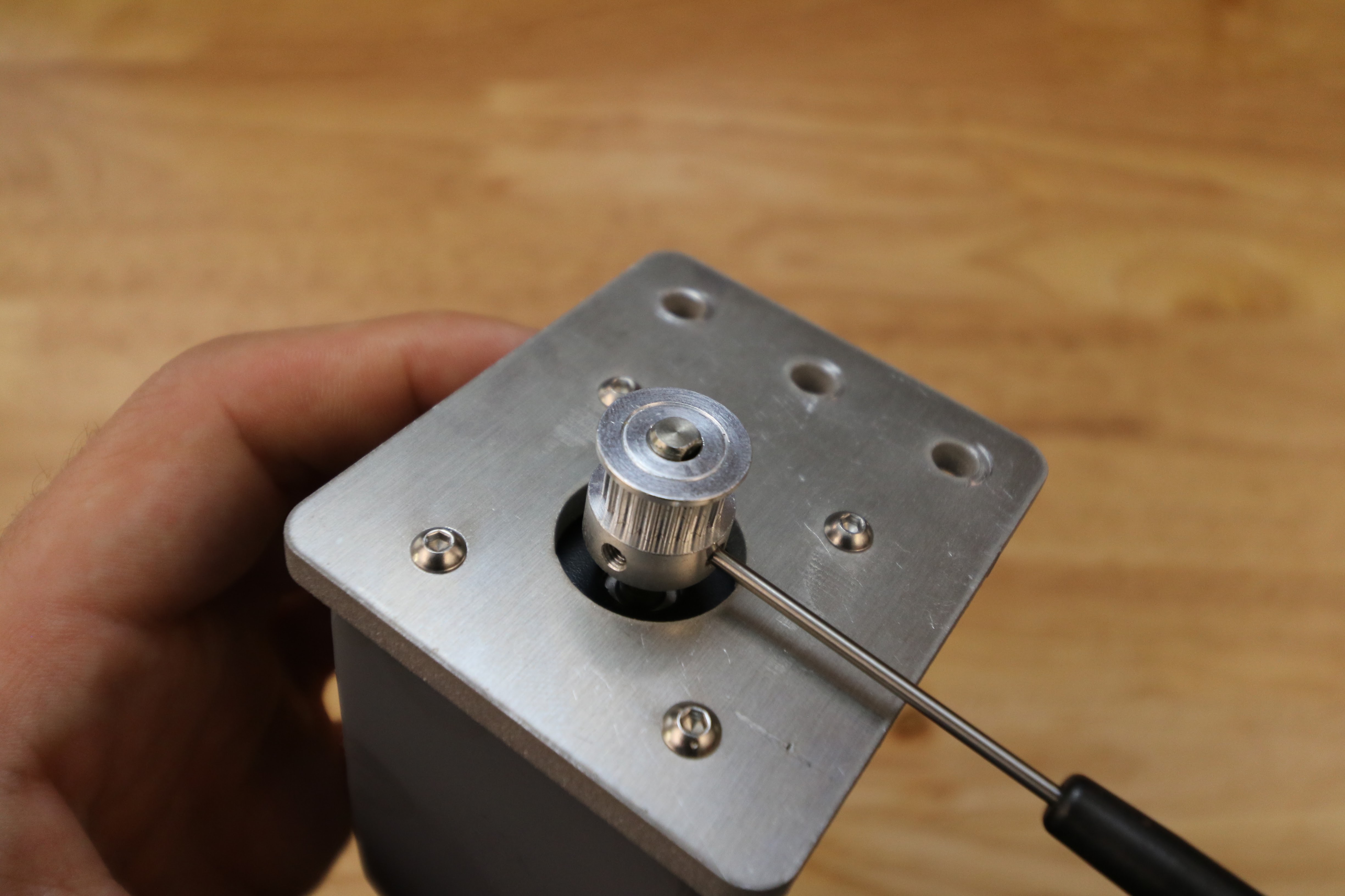
Lightly screw three M5 x 10mm screws and M5 tee nuts onto the motor mount plate. The tee nuts should be on the side of the plate opposite the motor.
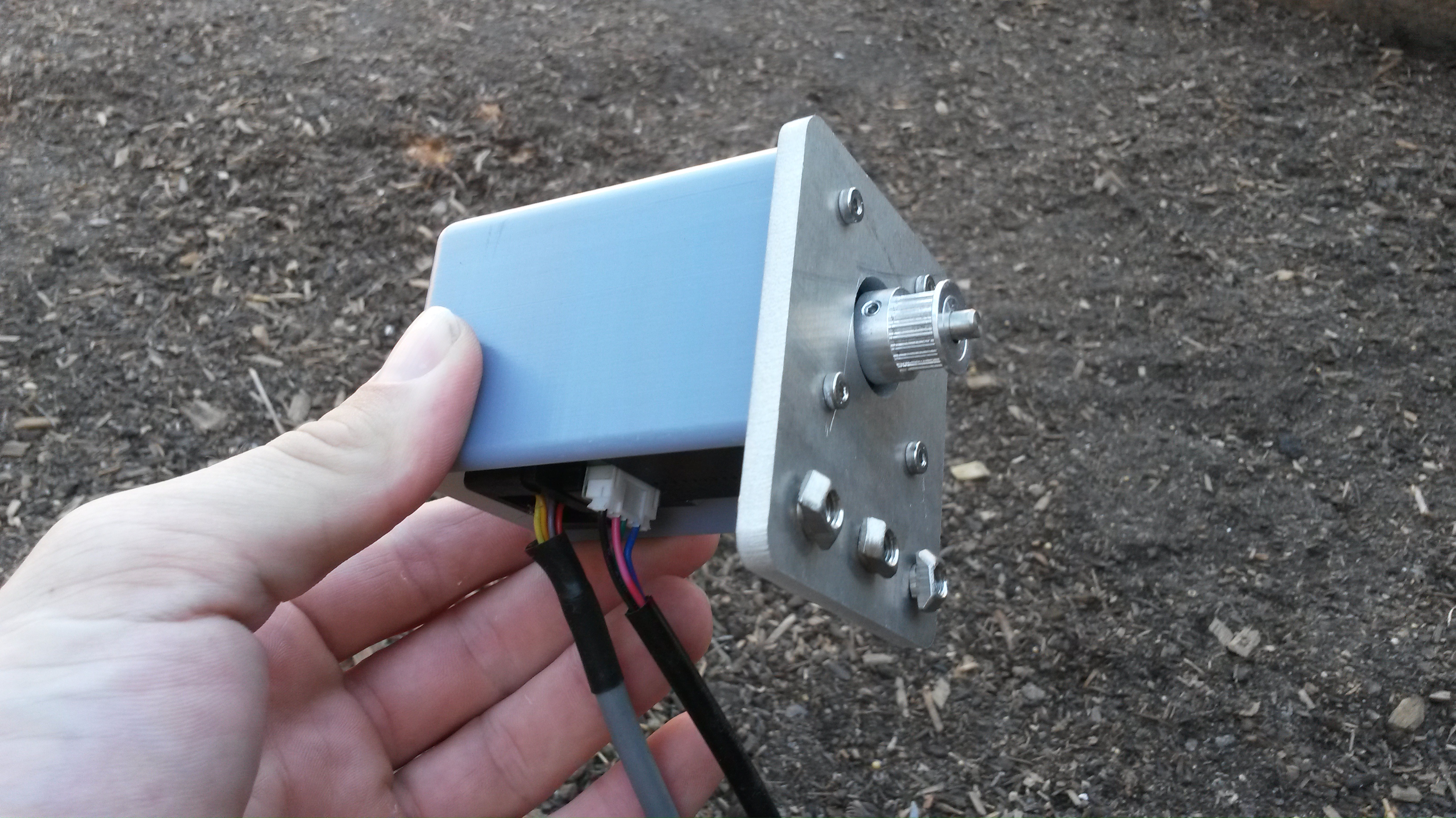
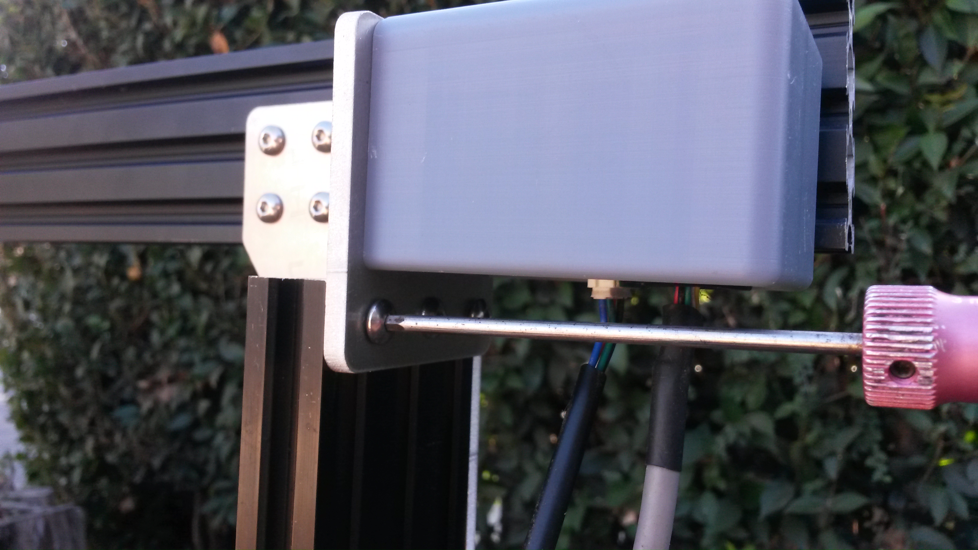
Slide the motor assembly onto the gantry column where you plan on mounting your electronics box. The motor shaft should be facing inwards to the bot. Use the 3mm hex driver to tighten the screws.
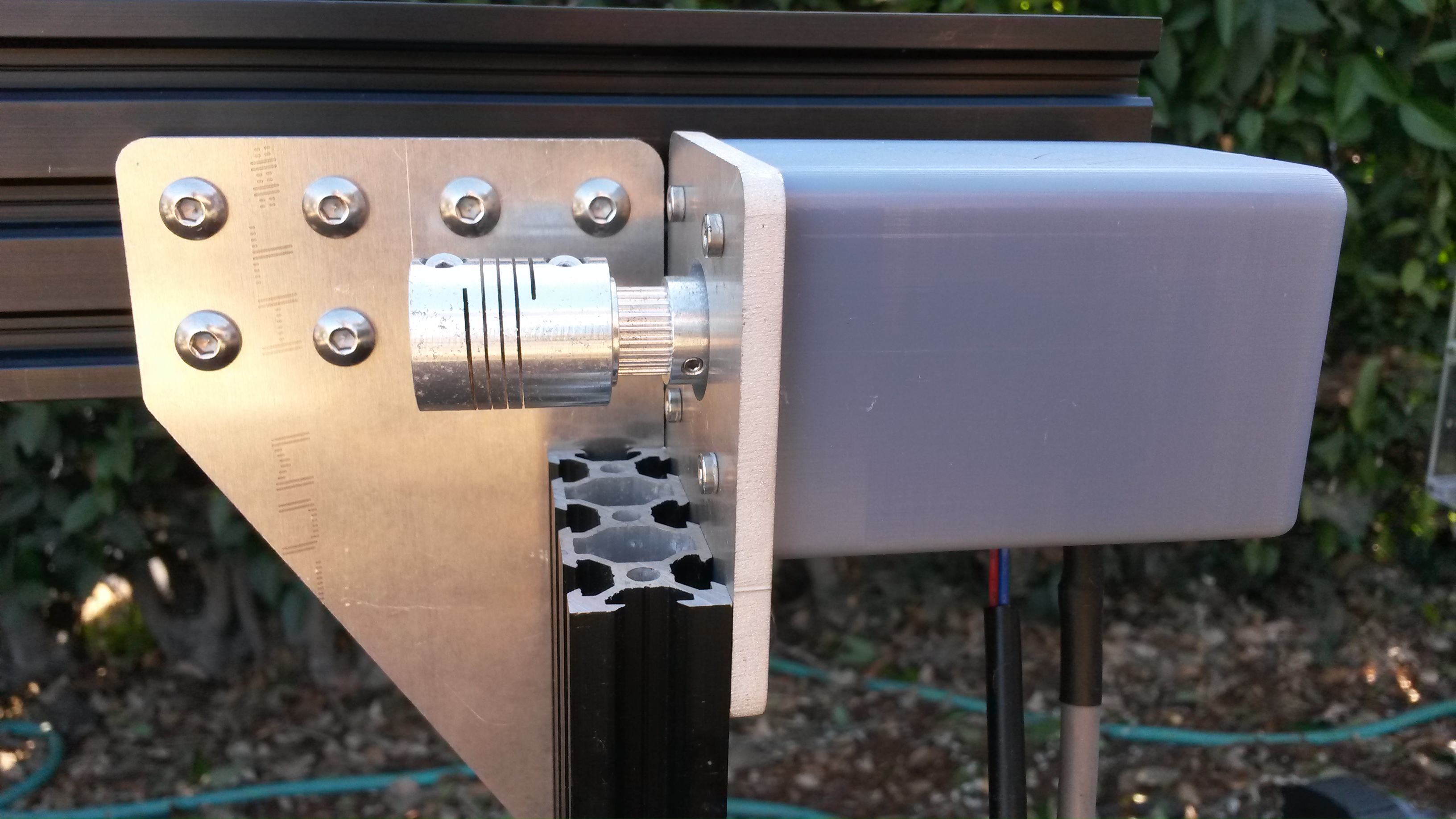
Slide a 5mm to 5mm flex coupling onto the gantry motor shaft and tighten it using the two M4 setscrews and a 2mm allen wrench.
Step 2: Attach the driveshaft support bearing
Lightly screw two M5 x 10mm screws and tee nuts onto the driveshaft support bearing bracket.
Step 3: Install the driveshaft and cable carrier supports
Insert two M5 x 10mm screws into a driveshaft support and then lightly attach M5 tee nuts.
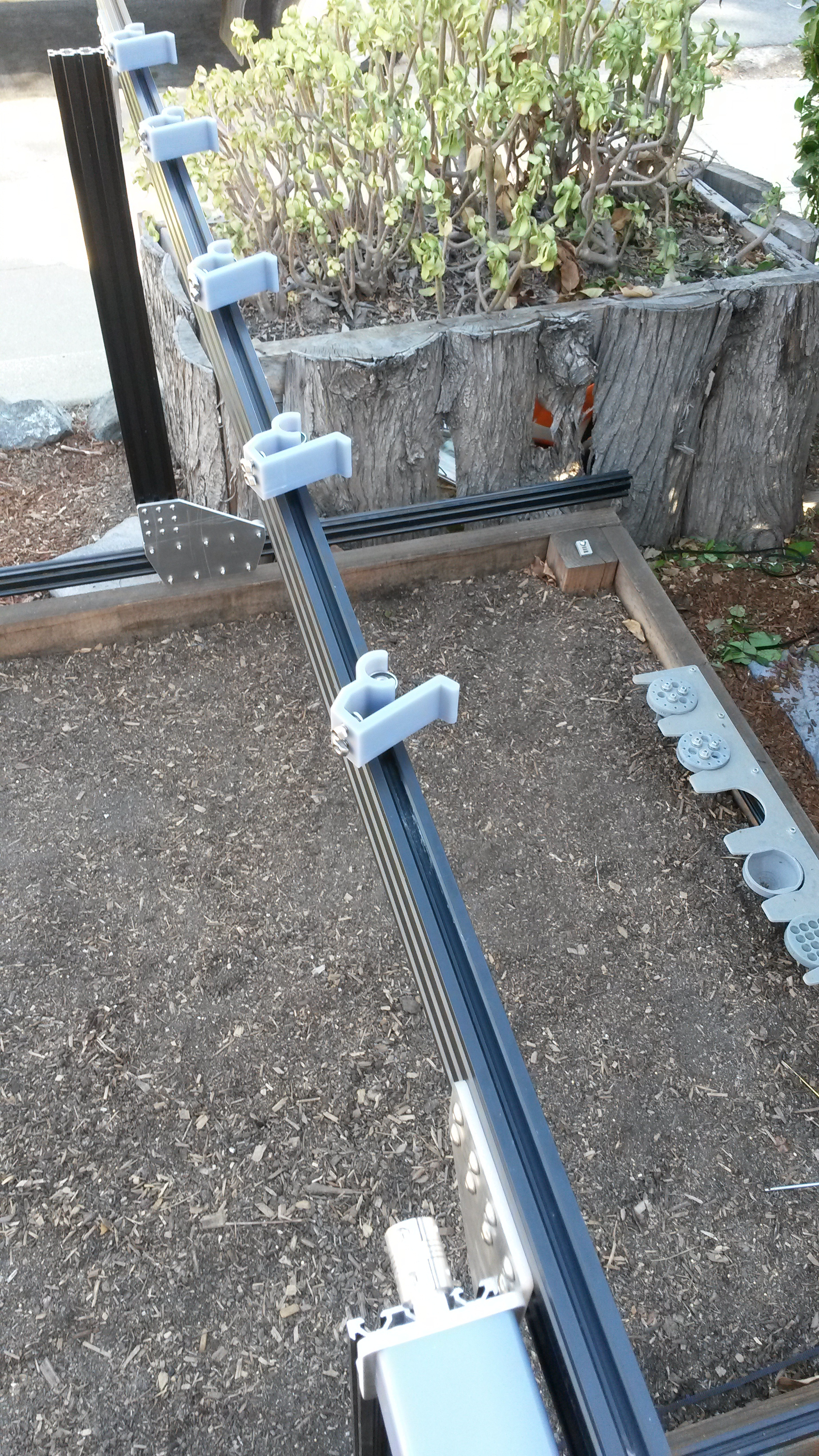
Evenly spaced
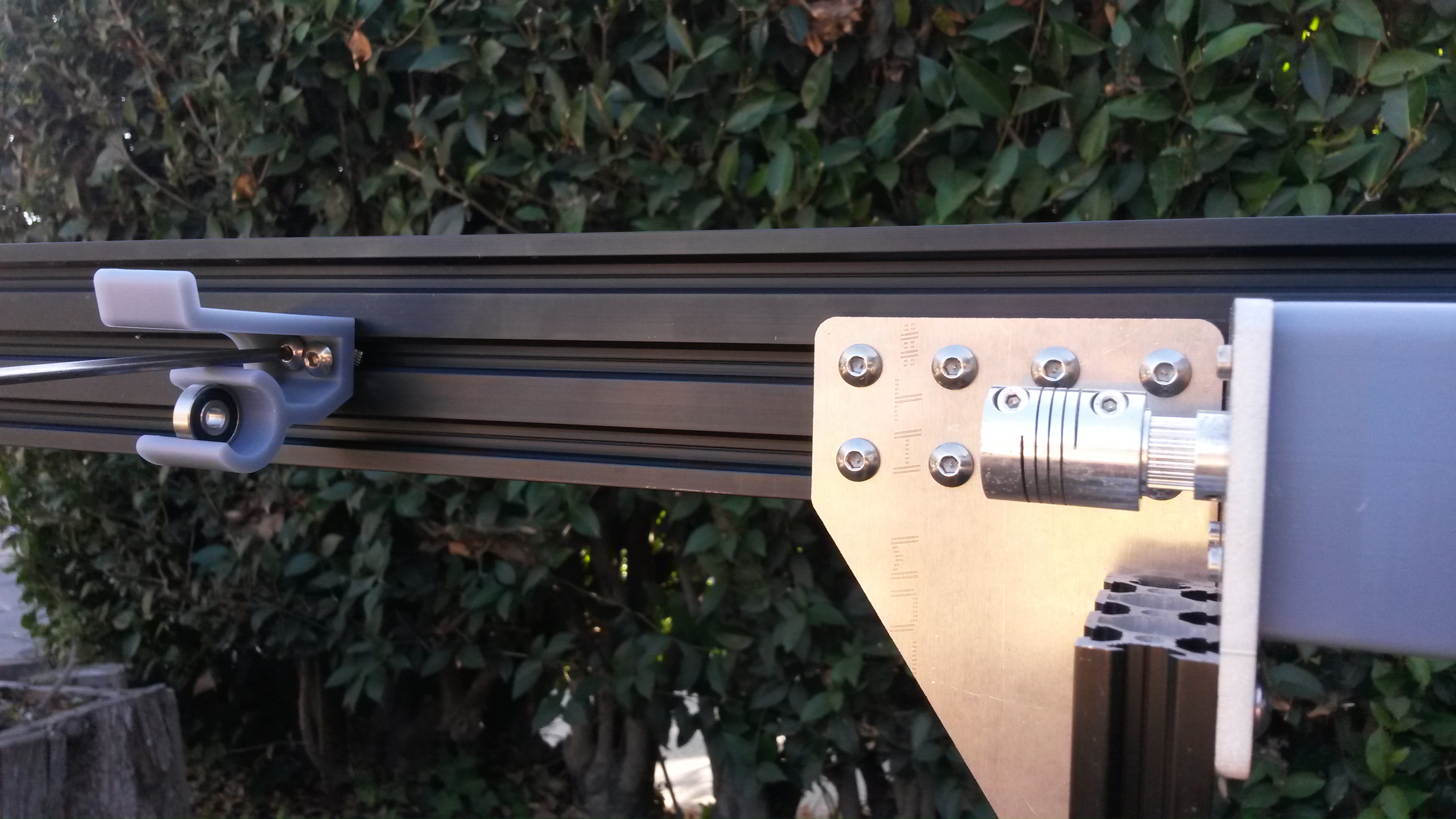
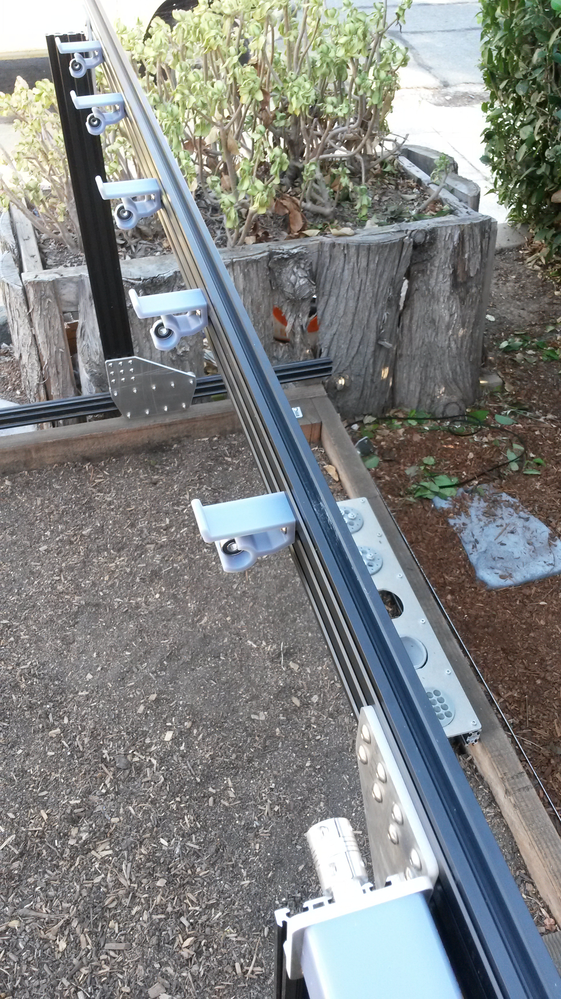
Keep in mind that there will be six total cable carrier supports in this slot on the main beam. You should space these components evenly along the beam. Don’t worry about getting the spacing right the first time - you can easily loosen them and make fine adjustments once they are all attached.
Place the assembly into the middle slot on the back side of the gantry main beam and use the 3mm driver to tighten the screw. Repeat the process for all six supports.

Step 4: Install the short cable carrier mounts
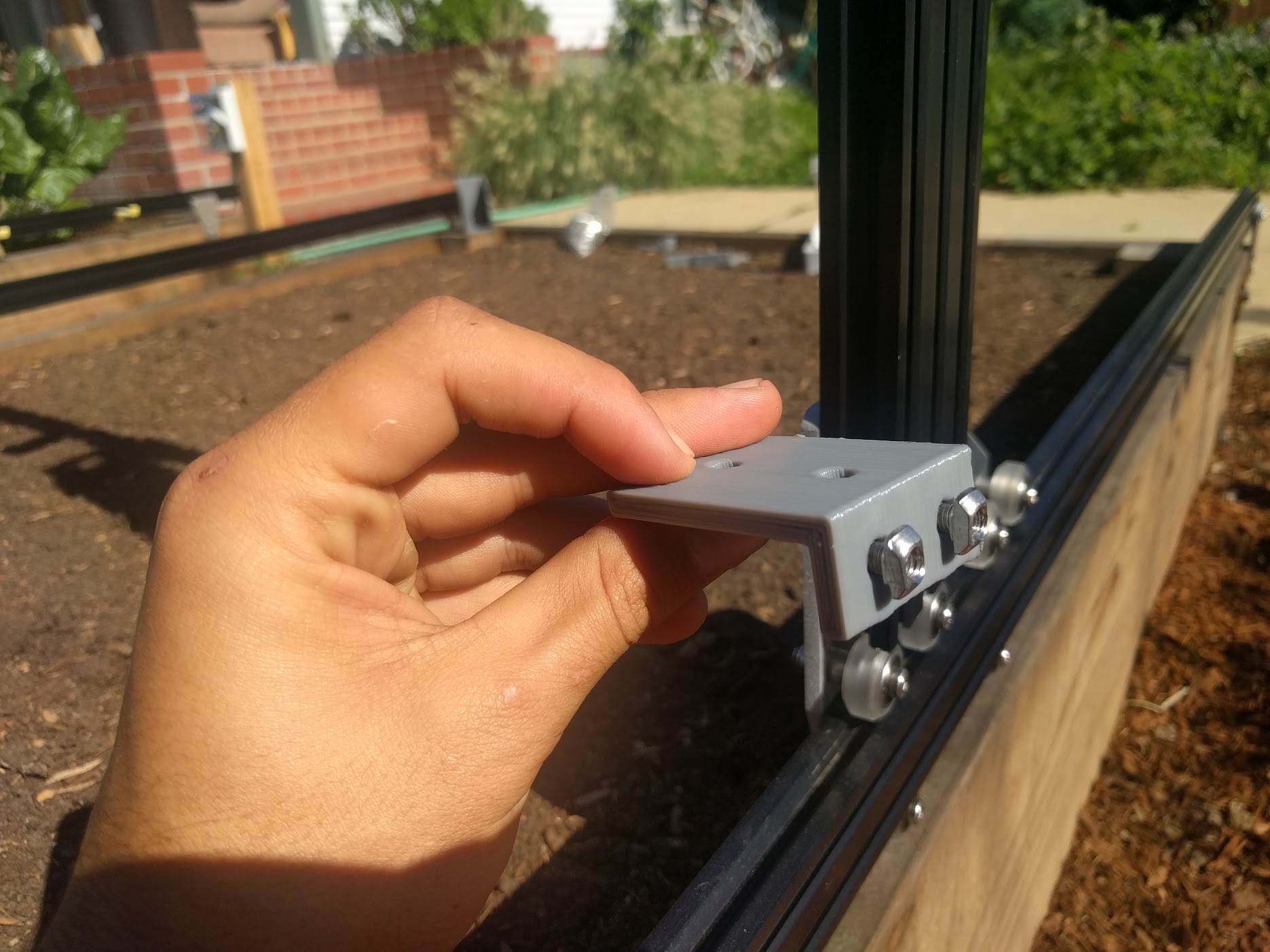
Insert two M5 x 10mm screws into a short cable carrier mount and lightly screw on two M5 tee nuts.
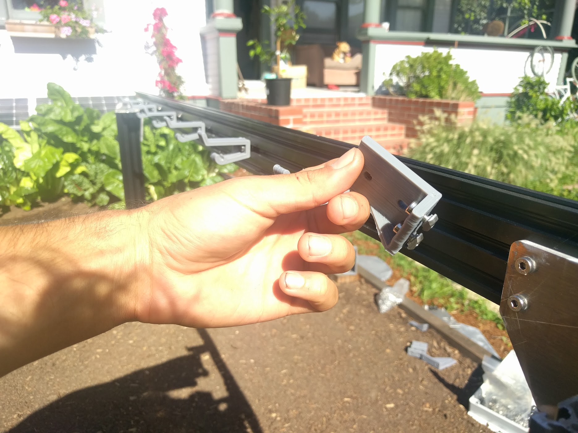
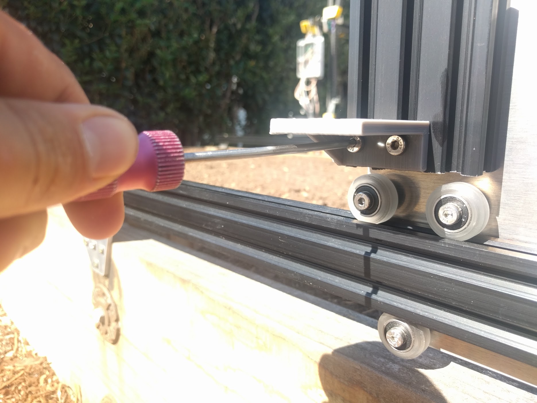
Place the assembly into the middle slot on the back side of the gantry main beam and tighten the two screws with the 3mm driver. The mount should be butted up the gantry corner bracket.
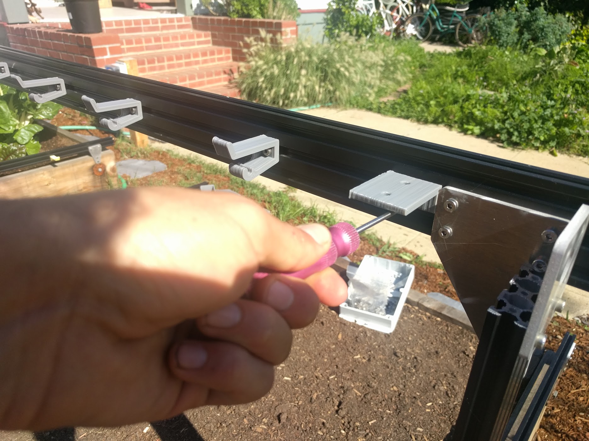
Repeat the process for another short cable carrier mount, and add it to the bottom of the left side gantry column.

Step 5: Insert the driveshaft
Slide five bearings onto the driveshaft.
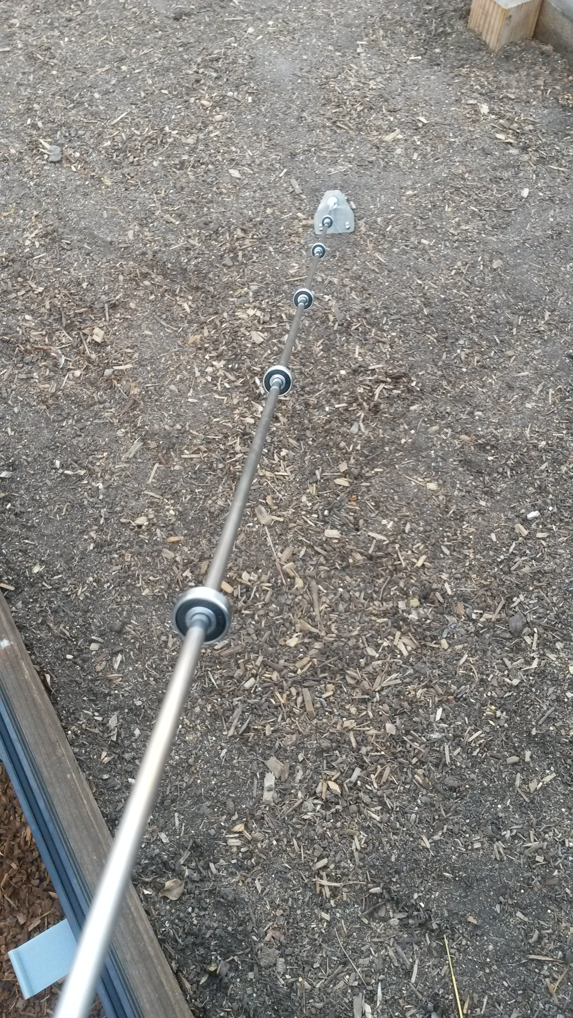

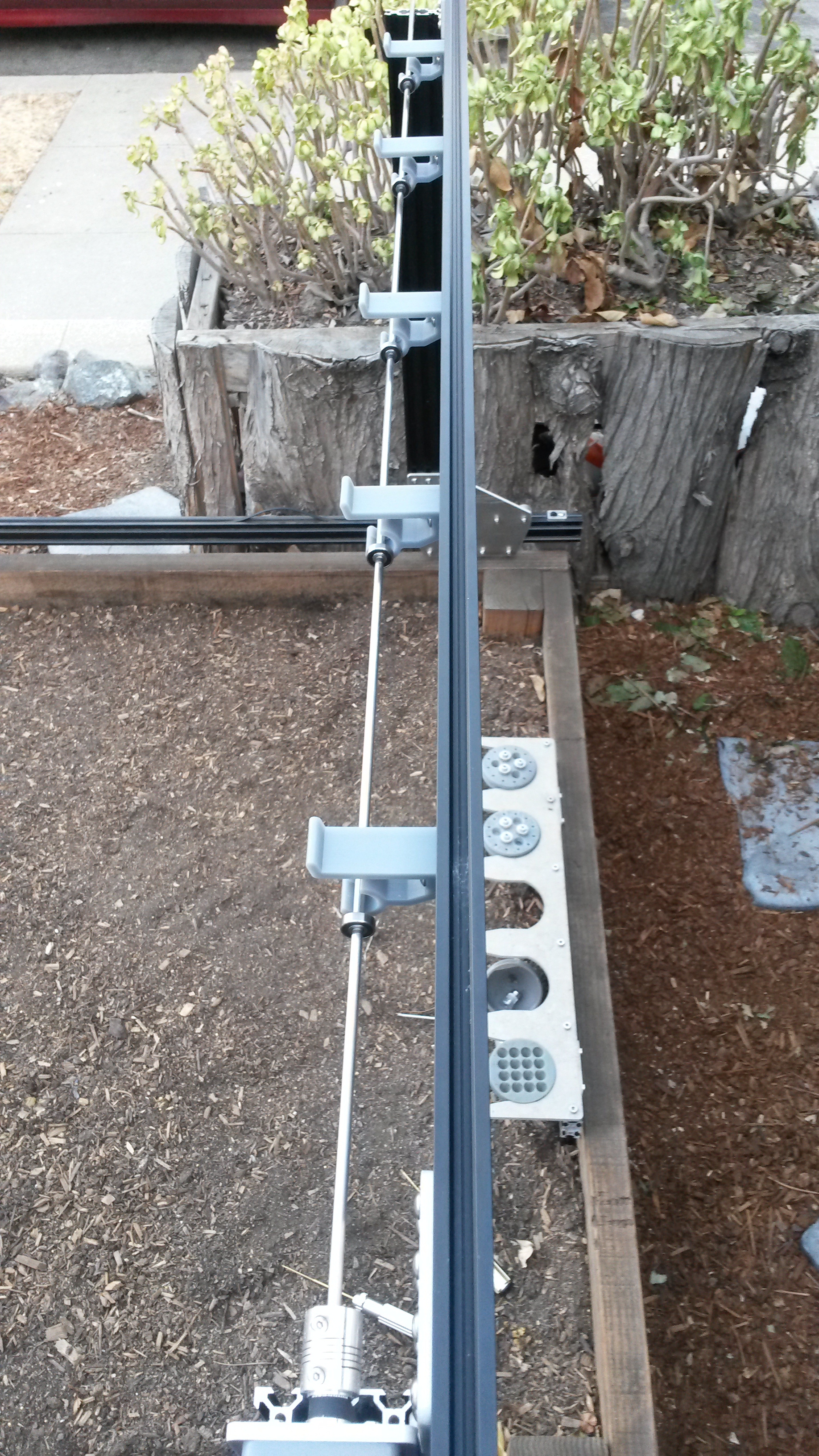
Place driveshaft into supports
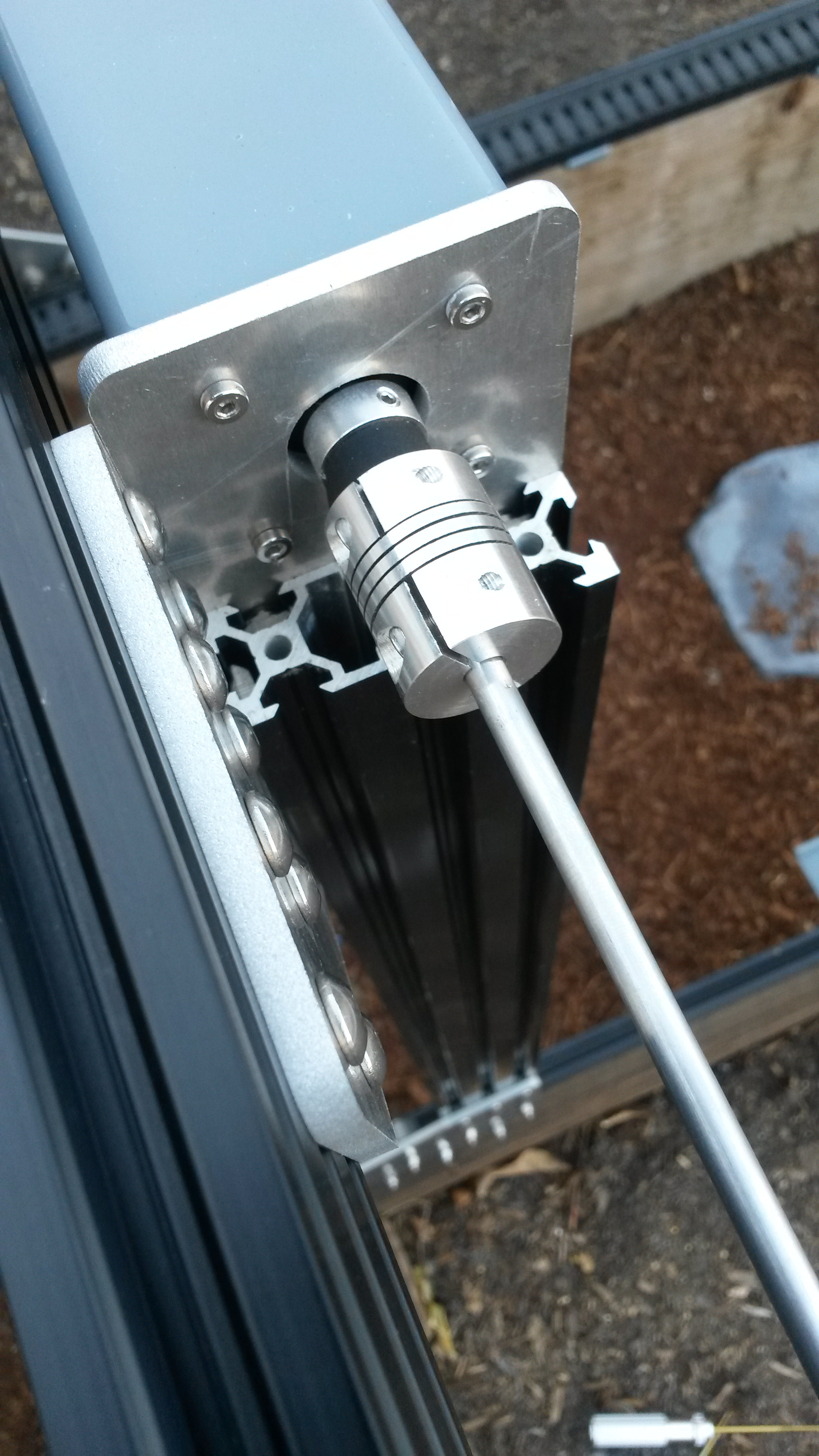
Insert driveshaft into flex coupling
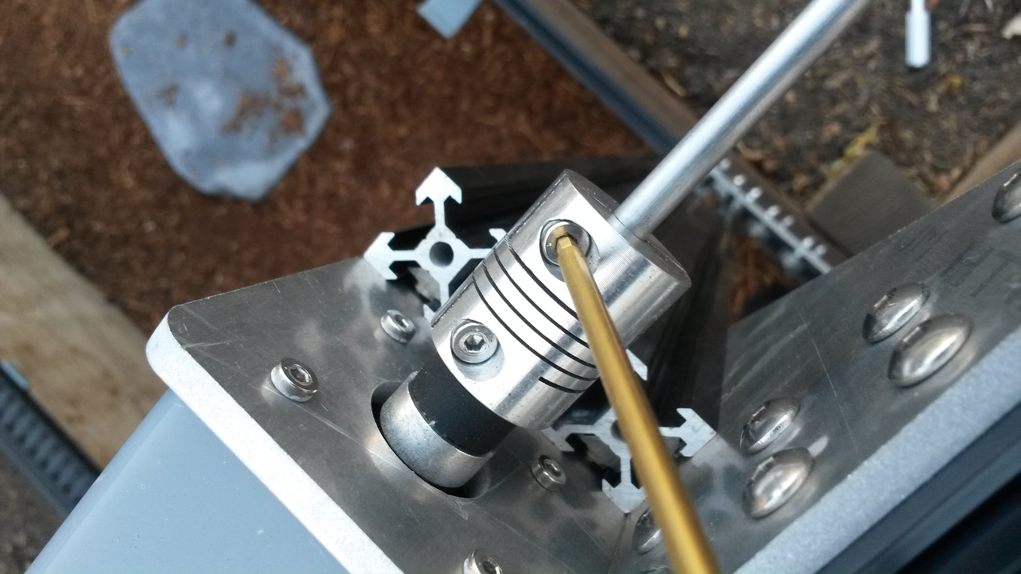
Tighten flex coupling onto driveshaft
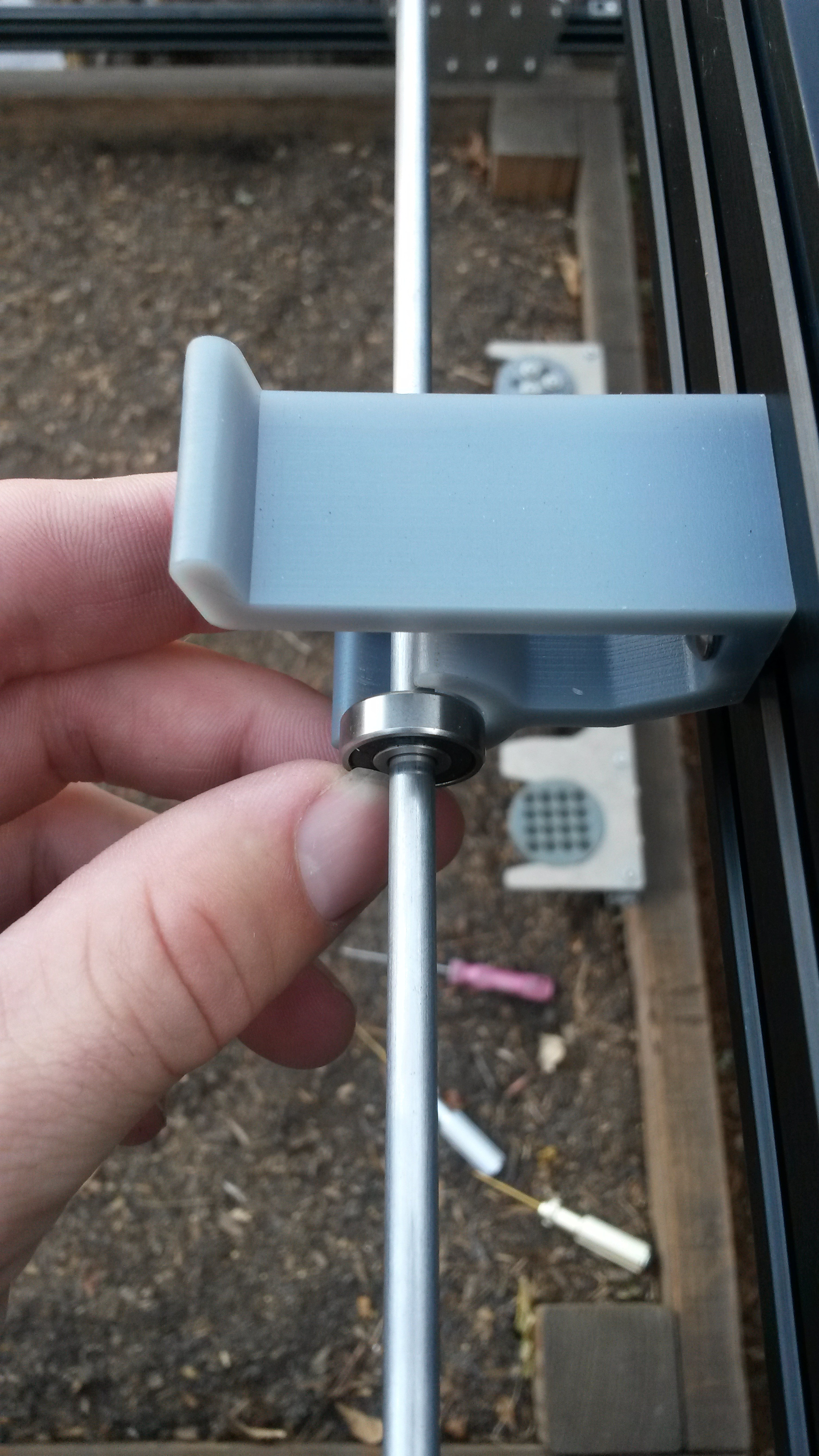
Push in bearing
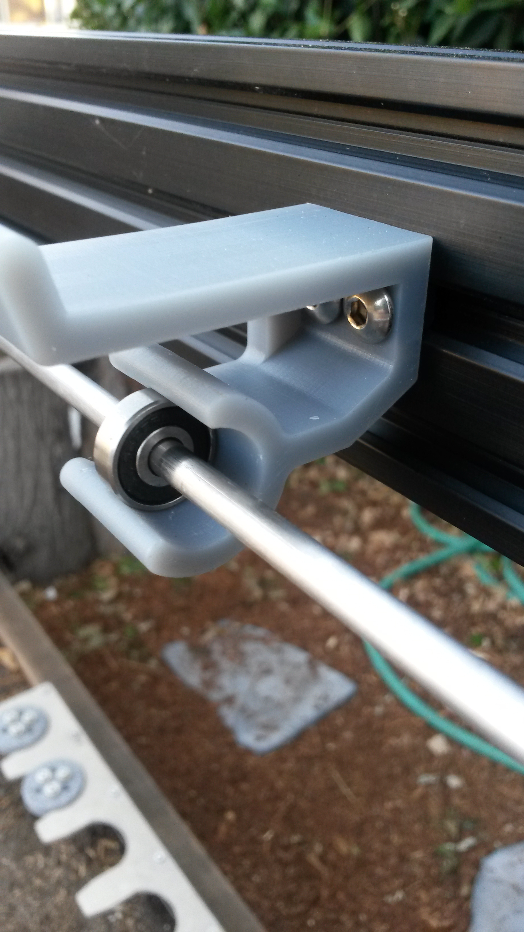
Driveshaft support bearing installed
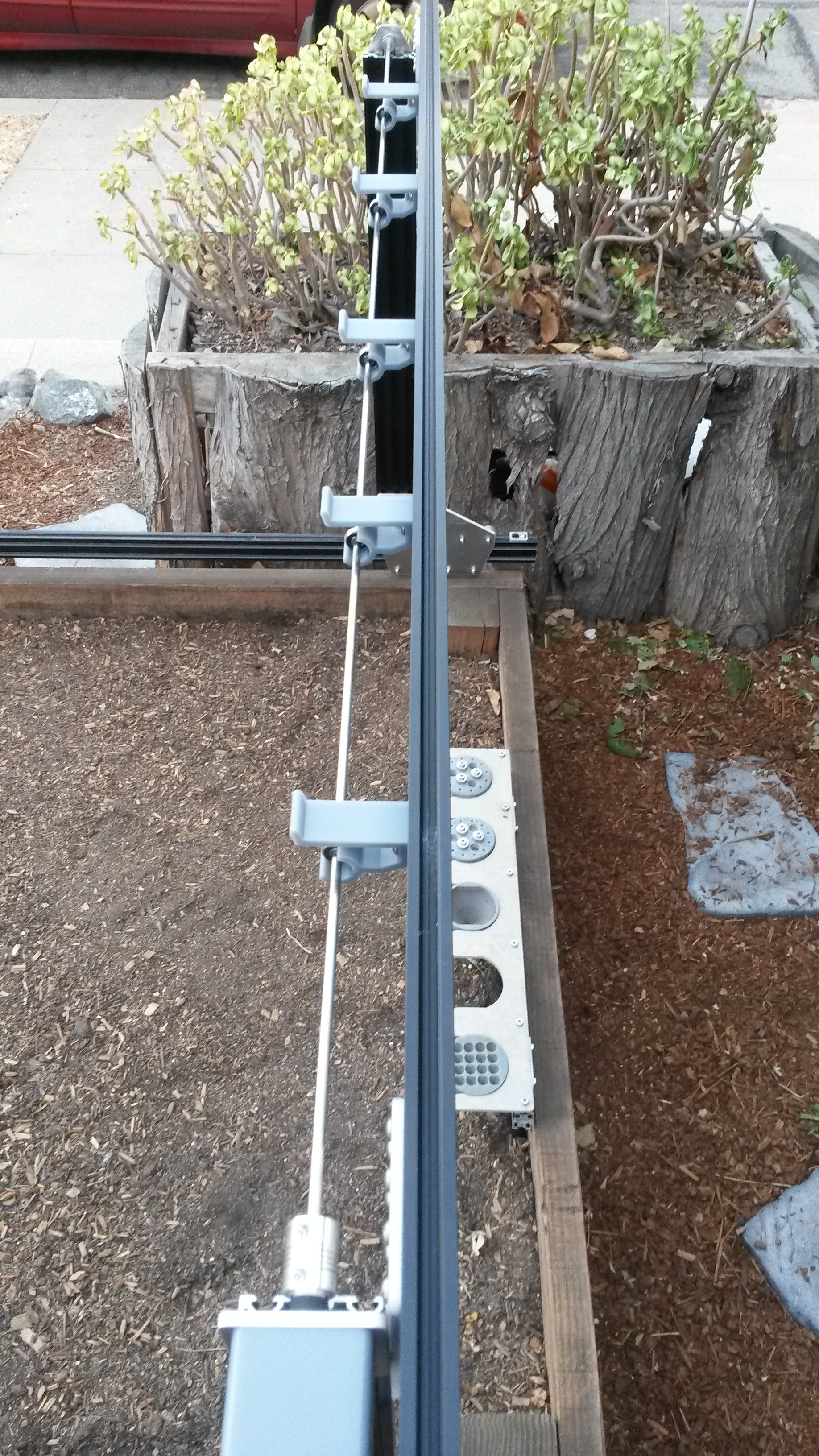
Repeat for all driveshaft supports
Onto the free end of the driveshaft, slide a GT2 pulley, then a 5mm x 16mm x 5mm bearing, and then a 5mm lock collar. Position the bearing inside the driveshaft bearing plate.
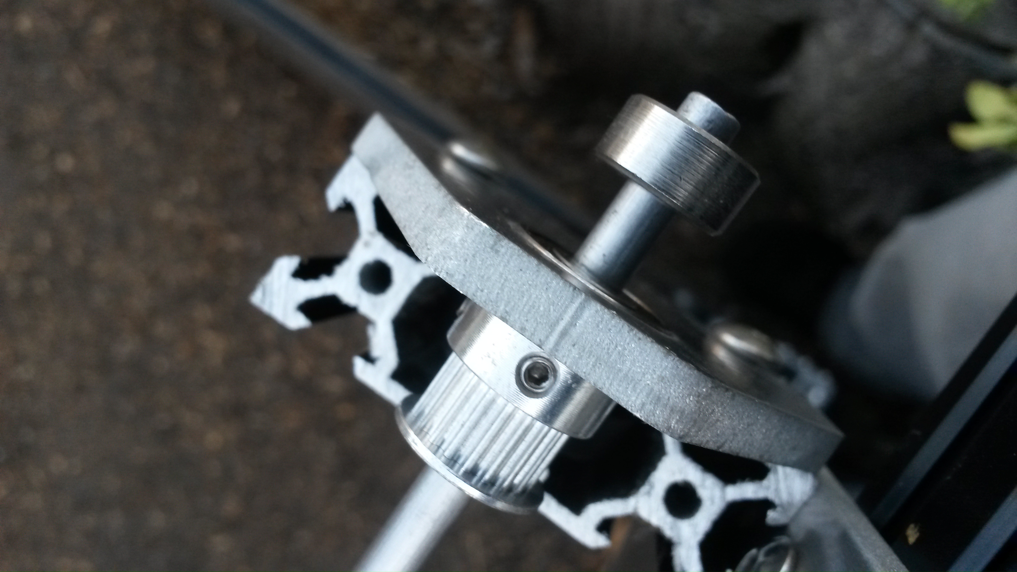
Add pulley, bearing plate, and lock collar
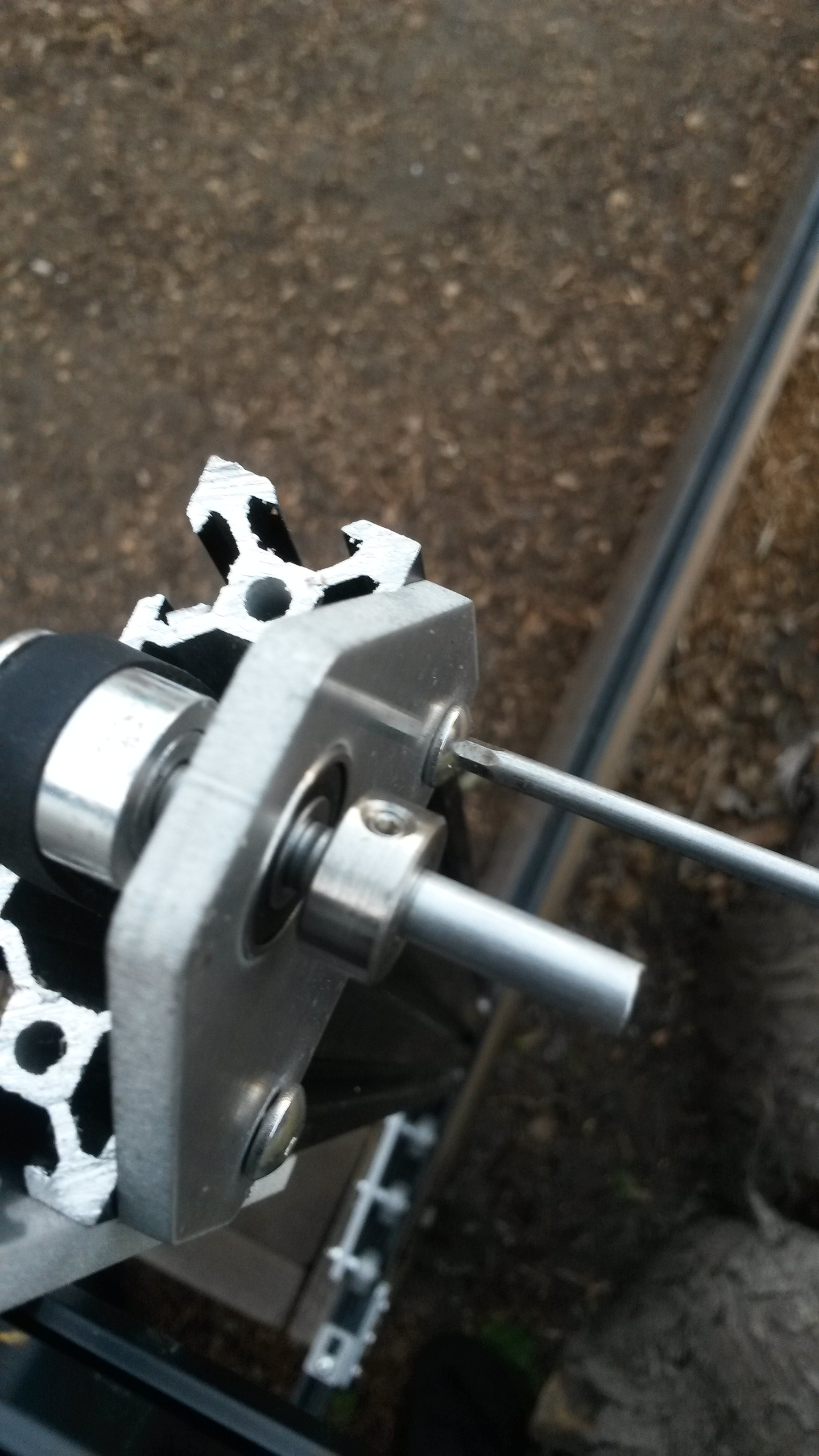
Tighten bearing plate
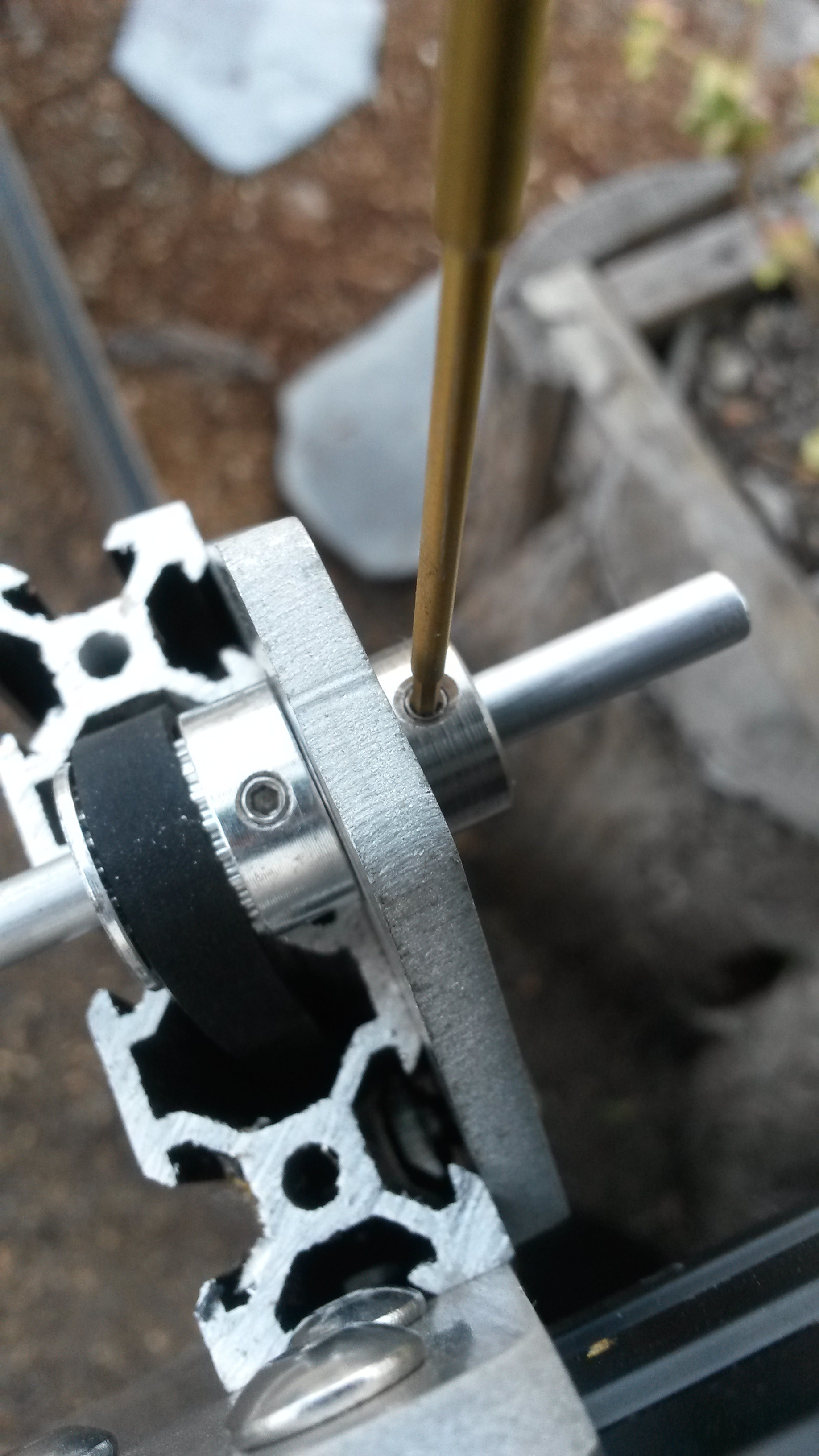
Tighten lock collar setscrew
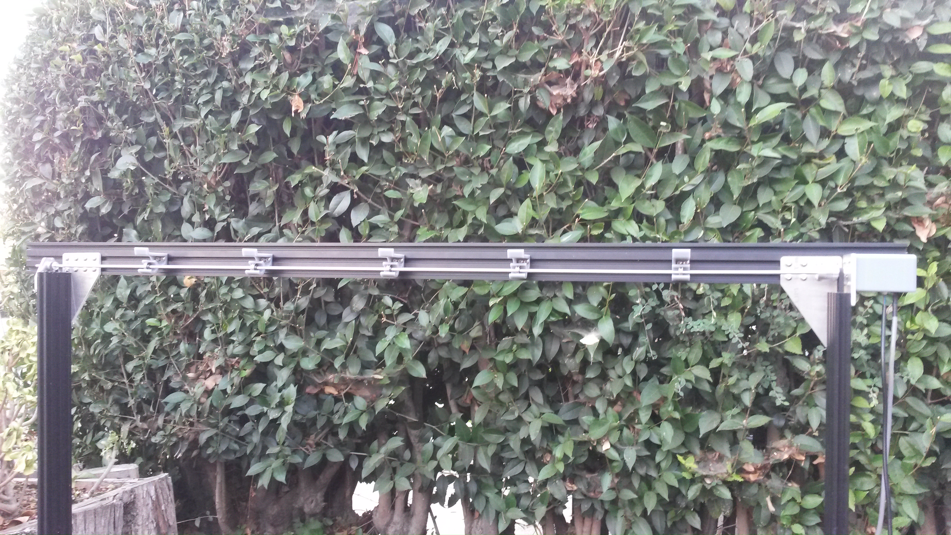
Installed driveshaft
Line 'er up
You may need to raise or lower your stepper motor plate and/or driveshaft bearing plate in order to line up all the driveshaft supports. What you’re looking for is a straight driveshaft that is parallel with the gantry main beam. it should not be bending in places or rubbing excessively on any of the supports.