Intro to FarmBot Genesis
DIY open-source hardware platform optimized for small-scale soil-based food production
FarmBot Genesis is the first FarmBot to be designed, prototyped, and manufactured. Genesis is designed to be a flexible FarmBot foundation for experimentation, prototyping, and hacking. The driving factors behind the design are simplicity, manufacturability, scalability, and hackability.
Genesis is a small scale FarmBot primarily constructed from V-Slot aluminum extrusions and aluminum plates and brackets. Genesis is driven by NEMA 17 stepper motors, an Arduino MEGA with a RAMPS shield, and a Raspberry Pi 3 computer. These electronics were chosen for their great availability, support, and usage in the DIY 3D printer world. Genesis can vary in size from a planting area as little as 1m2 to a maximum of 4.5m2, while accommodating a maximum plant height of about 1m. With additional hardware and modifications we anticipate the Genesis concept to be able to scale to approximately 50m2 and a maximum plant height of 1.5m.

FarmBot Genesis V1.0
Interested in helping develop FarmBot?
Share your ideas on the FarmBot forum, the FarmBot wiki, make suggestions to these docs, or contact us at suggestions@farmbot.io.
High Level Architecture
Tracks
Tracks are one of the components that really differentiate FarmBot technology from traditional free-driving wheeled tractors. The tracks are what allow the system to have great precision in an efficient and simple manner. There are many reasons of why Tracks are superior, a few of which are listed below.
- Tracks provide great precision and allow the the FarmBot to return to the same position repeatedly
- Any type of packing structure of plants can be created and managed
- Tracks take up less area than paths for tractor wheels and do not compact the soil
Gantry
The Gantry is the the structural component that bridges the two Tracks and moves in the X-direction via an X-Direction Drive System. Typically, it serves as a linear guide for the Cross-Slide and a base for the Y-Direction Drive System that moves the Cross-Slide across the Gantry in the Y-direction. It can also serve as a base for mounting other tools, electronics, supplies, and/or sensors.
Cross-Slide
The Cross-Slide moves in the Y-Direction across the Gantry. This motion provides the second major degree of freedom for FarmBots and allows operations such as planting to be done anywhere in the XY plane. The Cross-Slide is moved using a Y-Direction Drive System and functions as the base for the Tool Mount and Z-Direction Drive System.
Z-Axis
The Z-axis attaches to the Cross-Slide and provides the FarmBot with Z-Direction movement. It serves as the base for attaching the Universal Tool Mount and other Tools.
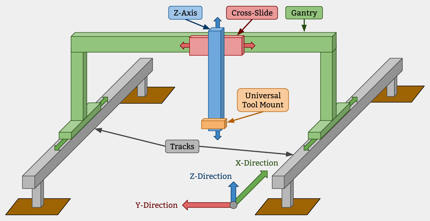
Z-Axis
Cross-Slide
Gantry
Universal Tool Mount
Tracks
X-Direction
Z-Direction
Y-Direction
Raised Tracks vs Low Tracks
For FarmBots to properly grow taller plants, the Gantry, Cross-Slide, Z-Axis, and Tools must have adequate vertical clearance from the plants. This can generally be accomplished in two ways:
- Using raised tracks and a low-profile gantry
- Using low tracks with a tall gantry
In general, using low tracks with a tall gantry is the better design, especially for larger applications because it saves on material cost, is less of an eyesore, blocks less sunlight, and would be easier to maintenance. However, in the case of a FarmBot being installed in a greenhouse or other structure, utilizing the existing walls to support the tracks higher may be a better solution.
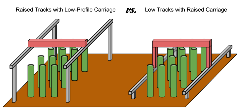
Raised Tracks with Low-Profile Carriage
vs.
Low Tracks with Raised Carriage
Design Principles
FarmBot Genesis is not your typical product. We’ve gone through great lengths to design the hardware to be durable, easily assembled and modified with common tools, constructed from largely off-the-shelf components, and manufactured with readily available processes and materials. Nothing about FarmBot speaks obsolescence or proprietary.
We’ve done this because at our core, we’re makers and hackers just like you. We enjoy tearing apart our gadgets and gizmos to fix them, improve them, and make them different and unique. So that’s what FarmBot Genesis is all about - empowering you to truly own FarmBot technology inside and out.
Go ahead and make your tracks longer, design a tool that electrocutes weeds, program FarmBot to spray water at the local cats, grow mushrooms, flowers, hydroponically, or on your living room wall! We can’t wait to see what you do with FarmBot.
We hope you’ll find our documentation useful and a great starting point for working with FarmBot and making it your own. If you ever have any questions, please head on over to the forum. Cheers!
What’s New in V1.0
With v0.9, we increased the size of the track, gantry, and cross-slide plates; used larger extrusions for the gantry (20x60mm instead of 20x40mm); and added more V-wheels to make the connections between sub-assemblies more rigid. All of these changes we’re added primarily to allow FarmBot to scale to an XL size (see V0.9 docs). However, after careful consideration we’ve decided to remove the XL version from the v1.0 design/docs in order to focus on a single product offering for our launch campaign. While the XL version of FarmBot Genesis may come back one day, it may also resurface in the form of a completely different FarmBot product line for the sake of optimizing each FarmBot for its intended scale.
Change Log
- Track plates are taller to accommodate the clearance between the bottom of the track extrusions and the top of the raised bed while giving ample room for screwing the plate to the supporting infrastructure
- Track plates have designed-in notches that indicate where to position them vertically on supporting infrastructure so that a tape measure or ruler is not needed for assembly
- Gantry corner plates are slightly taller to bring back enough clearance for the cross-slide to be removed from the gantry main beam without removing the main beam from the columns
- Horizontal motor housings on the cross-slide and gantry have been completely re-designed to better protect the ends of the motors and the rotary encoders from rain
- Introduction of the belt clip that allows the track and gantry belts to be easily secured to the extrusions without damaging the belts
- Increased the thickness and length of the gussets on the drag chain mounts, cable carrier supports, and driveshaft supports
- Increased the size of the slot on the cross-slide and the z-axis motor mount for the motor and encoder wires to be passed through more easily
- Increased the tolerance of the driveshaft bearing plate bearing hole, and the eccentric spacer holes on the gantry main plates and cross-slide plate
- Incorporated a bearing into the driveshaft supports
- Added an extra flange to the z-axis motor mount to increase strength in its connection to the z-axis extrusion
- Completely re-designed the z-axis motor cover to accommodate larger motors/encoders and their wires, and to maintain a secure connection to the z-axis extrusion
- Increased the width of the cross-slide plate to accommodate a larger z-axis cable carrier (now 15x40mm to match the other cable carriers)
- Added more wheels to the cross-slide plate and to the gantry plates to increase rigidity
- Introduced the soil sensor tool
- The seed injector tip has been lengthened and re-positioned into the center of the tool
- Began tumble polishing all plates to remove burrs and manufacturing marks and improve the overall aesthetic of the plates
- Decreased the size of the tool bay for ease of tumble polishing. It now accommodates only three tools instead of five, though each kit will now include two tool bays instead of one for a net gain of one slot.
- Introduced small mounting plates for the tool bay
- Switched from low-profile M5 socket head screws to M5 button-head style screws. The new screws still have 3mm hex drives, but have a lower profile (2.75mm instead of 3.5mm) that provides better clearance between lower gantry v-wheel screws and track plates. They also have larger diameter heads (9.5mm from 8.5mm) that distribute loads more evenly and provide more secure connections, especially for the plastic components.
- Modified the UTM so that the magnets lie closer to the tool. This modification was possible due to the switch to the lower-profile button head screws.
- The UTM is significantly thinner while the UTM cover is significantly taller to provide more space for the wiring and tubing. The FarmBot logo has been moved from the UTM to the cover.
- Removed the o-ring groove on the UTM’s liquid/gas ports and re-designed the ports to be injection mold-able.
- Switched from circular profile o-rings to square profile o-rings for more direct sealing of the liquid/gas ports and for compatibility with the new port design.
- Added an inline pressure regulator to improve performance of the watering nozzle tool and prevent leaking.
- Added cable clips near the electronics box to better manage cables and tubing
Past Versions
In development
Genesis is currently being developed and has undergone several versions. We encourage skimming through the older versions to understand how we arrived at the latest design iteration.
V1.0
Major changes: track plate improvements, new seed injector design, larger z cable carrier, new motor housings and z motor mount, larger cross-slide and gantry plates with more v-wheels, new tool bay, new seed bin, stronger cable carrier supports, introduced cable management clips, introduced belt clip plates, significant modifications to the UTM and UTM cover, switched to button head M5 screws.
V0.9
Major changes: larger plates, more v-wheels, larger gantry extrusions for added rigidity, introduced the weed suppressor tool
V0.8
Major changes: all corrosion resistant design; upgrade to 5mm thick plates; improvements to the UTM, cable carrier brackets, and electronics enclosure
V0.7
Major changes: removal of endstops, stronger z-axis motor mount, added z-axis cable carrier, track plates and gantry corner plates redesign, upgraded universal tool mount to support 6 liquid lines and 12 electrical connections, quick access electronics enclosure, larger cable carriers
V0.6
Major changes: reliability improvements to the universal tool mount
V0.5
Major changes: rotary encoders on motors, integrated water, vacuum, and liquid amendments into universal tool mount, part simplification
V0.4
Major changes: electronics enclosures/housings, cable carrier cable management, magnetic universal tool mount design
V0.3
Major changes: wire and trolley cable management, part simplification
V0.2
Major changes: endstop integration, custom brackets and plates, universal tool mount
V0.1
Focused on being a quick and easy first prototype, V0.1 was constructed from all off-the-shelf components