Tools
Tool Spec
Want to design and make your own tools for FarmBot? Follow these instructions to ensure compatibility with the universal tool mount (UTM), the tool bay, and your FarmBot’s electronics.
Unlimited possibilites
These specs must be followed to ensure your tool works with a stock FarmBot. However, don’t shy away from experimentation and the possibility of modifying your UTM, tool bay, or electronics to accommodate your desired tool design. FarmBot is yours to play with and modify.

Hardware Requirements
Design your tools to meet these hardware specifications to ensure compatibility with FarmBot. Additionally you will need to design your tool so that it can be produced with available tools, processes, and materials; and stand up to the outdoor environment and other expected stresses.
Required Components
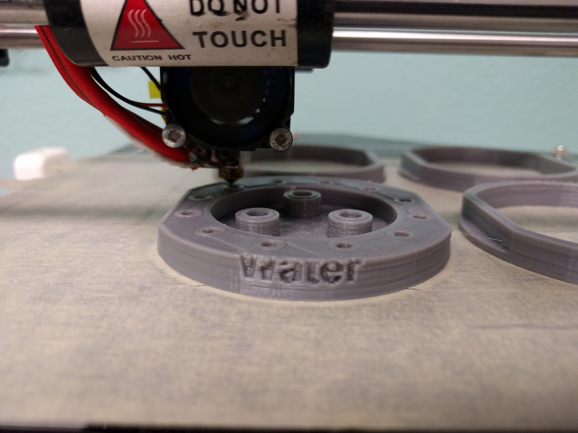
- Plastic “tool base”
- Three 15 x 5 x 5 mm ring magnets secured with M5 screws and locknuts
- Two M3 electrical screws and locknuts, and a small jumper wire used for tool verification
Specs
- Max weight: 2 kg / 4.5 lbs
- Max height: 200 mm / 8 inches
- Max diameter: 100 mm / 4 inches
Size, shape, and layout
Tools must have the correct physical dimensions and component layout on the top face so that they can correctly couple and de-couple with the UTM as well as slide in and out of the tool bay. Study the drawings below to ensure you design your tool accordingly.
Start with a CAD model
Want to get a headstart on design? Download a tool base CAD model from CAD Models.
This 3D model shows the features of our downloadable tool base:
Electrical Requirements
The stock UTM has a specific electrical pin (screw) layout that covers most tool needs. Your tool will need to include electrical screws and wiring that matches up with the UTM for your use case. All tools need pins B and C so that FarmBot knows if it has correctly mounted and dismounted the tool. Beyond that, your tool may have no other electrical needs, or many. Use the pin mapping table below for reference when wiring up your tool.
Pin Mapping
| UTM Pin | is connected to | and used for |
|---|---|---|
| A | Ground (0V) on Arduino/RAMPS | Ground |
| B | +5V on Arduino/RAMPS | Tool Verification (Required) |
| C | Pin D16 on Arduino/RAMPS - Digital-In | Tool Verification (Required) |
| D | Pin D17 on Arduino/RAMPS - Digital I/O | Data tool functions such as servo control or sensor reading |
| E | Pin D23 on Arduino/RAMPS - Digital I/O | Data tool functions such as servo control or sensor reading |
| F | Pin D8 on Arduino/RAMPS - High power output | High power tool functions such as motors or lasers |
| G | Pin 20 on Arduino/RAMPS - I2C data (SDA) | Complex tooling requiring addressing of commands |
| H | Pin 21 on Arduino/RAMPS - I2C clock (SCL) | Complex tooling requiring addressing of commands |
| I | USB VCC (+5V) | USB based tools |
| J | USB D- (Data -) | USB based tools |
| K | USB D+ (Data +) | USB based tools |
| L | USB Ground (0V) | USB based tools |
Change Log
- Now using button head M5 screws
Room for Improvement
Nothing to see here!