Assemble the Tracks
Step-by-step instructions for assembling FarmBot’s tracks
- Step 1: Gather the Parts and Tools
- Step 2: Layout the Track Extrusions
- Step 3: Attach a Track End Plate
- Step 4: Attach a Track Joining Plate
- Step 5: Attach the first Track Extrusion
- Step 6: Attach the second Track End Plate and Extrusion
- Step 7: Install the other track
- Step 8: Add a short cable carrier mount
- Step 9: Add cable carrier supports
2 hours
This is the estimated time it will take to assemble the tracks.
Supporting Infrastructure Required
These assembly instructions assume that you already have supporting infrastructure in place, such as a raised bed.
Step 1: Gather the Parts and Tools
Gather all the parts from the table below and lay them out in a logical manner. To complete the assembly, you will also need the following tools:
- 3mm allen (hex) wrench
- Number 2 phillips screwdriver or electric drill with a Number 2 phillips driver bit
| Qty. | Component |
|---|---|
| 4 | Track Extrusions (20 x 40 x 1500mm) |
| 4 | Track End Plates |
| 2 | Track Joining Plates |
| 20 | 1 inch #2 Phillips Wood Screws |
| 36 | M5 x 10mm Screws |
| 2 | M5 x 16mm Screws |
| 2 | M5 Washers |
| 36 | M5 Tee Nuts |
| 2 | M5 Locknuts |
| 1 | 1.5m Cable Carrier |
| 1 | Cable Carrier Mounting Bracket |
| 10 | Cable Carrier Supports |
| 2 | 5m GT2 Timing Belt |
Step 2: Layout the Track Extrusions
Lay out all of the track extrusions in the location that you want to attach them to your supporting infrastructure. Make sure that extrusions are fully butted against each other. This will help you attach the plates in the correct location.
Overhang is a-ok
The ends of your tracks do not have to match up perfectly with the ends of your supporting infrastructure. A little overhang or coming up short is just fine.
Step 3: Attach a Track End Plate
Position a track end plate as shown below and screw it into the supporting infrastructure with three wood screws.
Vertically aligned
All of the track extrusions must be the same height and aligned along their length so that the gantry can move across the tracks smoothly. This means that all of the track end plates and track joining plates need to be vertically aligned.
We’ve added small notches into the track end plates and track joining plates so that you can position the plates with perfect vertical alignment with respect to your supporting infrastructure and each other. You should only use these notches if the top edge of your supporting infrastructure is level and straight.
If the top edge of your supporting infrastructure is not level or straight, then you will need to manually ensure that your track plates are vertically aligned with other means. Because the gantry has wheels that ride on the bottom face of the track extrusions, you need to ensure that the bottom of the track extrusion will be at least 25mm away from the top of the supporting infrastructure so that the wheels have adequate clearance.
Lightly screw three M5 x 10mm screws and tee nuts to the track end plate. Orient the tee nuts horizontally.
Step 4: Attach a Track Joining Plate
Position a track joining plate such that one half of it will be able to attach to each track extrusion and so that it is vertically aligned with the first track end plate. Screw the plate into the supporting infrastructure with four wood screws.
Lightly screw four M5 x 10mm screws and tee nuts to the track joining plate. Orient the tee nuts horizontally.
Step 5: Attach the first Track Extrusion
Lift the track extrusion and position the lower V-slot onto the tee nuts of the track end plate.
Lightly tighten one of the M5 x 10mm screws using the 3mm hex driver to prevent the extrusion from falling off, while still allowing it to move loosely.
Lift the other end of the track extrusion and position the lower V-slot onto the tee nuts of the track joining plate. Verify that the track extrusion is positioned correctly, and then tighten all five of the M5 x 10mm screws that hold it in place.
For Longer Tracks...
If you are installing more than two extrusions worth of tracks, then repeat steps 4 and 5 with more track joining plates and extrusions.
Step 6: Attach the second Track End Plate and Extrusion
Follow the instructions in Steps 3 and 5 to attach the second track end plate and second track extrusion.
Extrusion alignment is key
Position your track extrusions tightly together at the middle of the track joining plate. The top and bottom of the extrusions must be flush so that the gantry can move across the tracks smoothly. Ensure that your extrusions are parallel (no kink where they meet) by looking down the length of the tracks. If there is a kink, adjust the track extrusions and plates accordingly.
See the gap in the track extrusions? You don’t want that!
Perfectly aligned track extrusions are key to smooth gantry movements!
Step 7: Install the other track
Repeat steps 3 thru 6 for the other track. Ensure that the tracks are parallel to each other prevent the gantry from binding.
Step 8: Add a short cable carrier mount
Insert two M5 x 10mm screws into a short cable carrier mount and lightly screw on two M5 tee nuts.
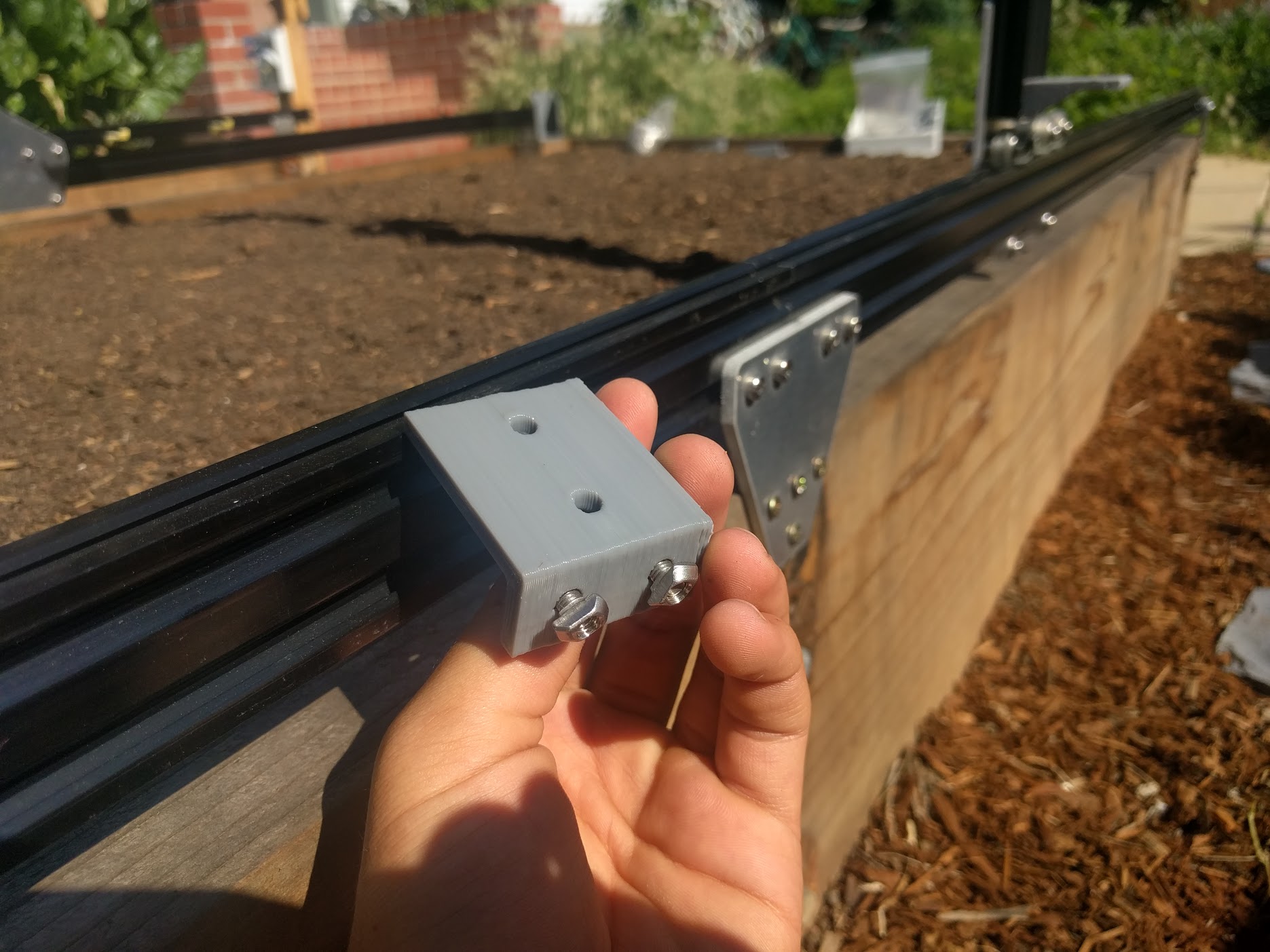
Note that this photo was taken from the back-side of FarmBot.
Place the assembly into the lower slot of the left side track. It should be butted up against the track joining plate. Use the 3mm driver to tighten the screws.
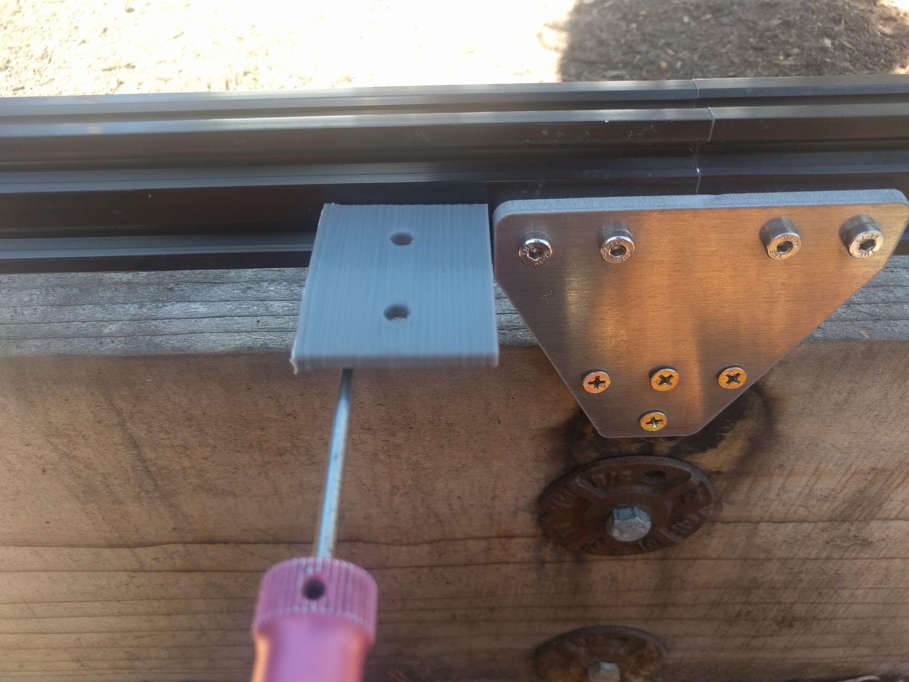
Step 9: Add cable carrier supports
Position the 10 cable carrier supports evenly along the tracks. Keep in mind that the short cable carrier mount acts as a support, so there will be 11 total components supporting the cable carrier. There should be five on each track extrusion.
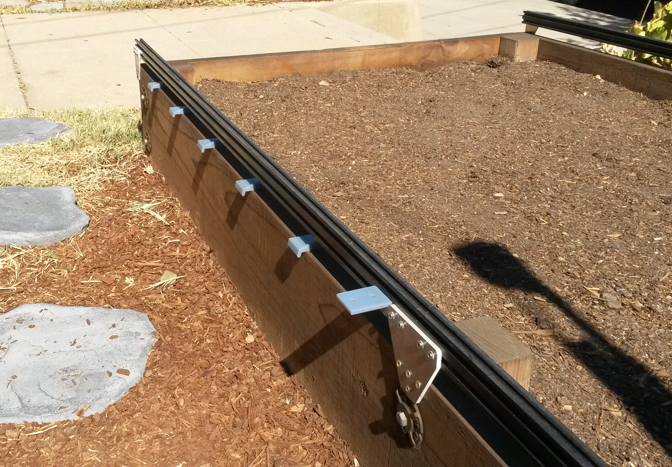
Insert two M5 screws into the cable carrier support and lightly attach M5 tee nuts. Then use the 3mm driver to tighten the assembly into the lower slot of the track extrusion.
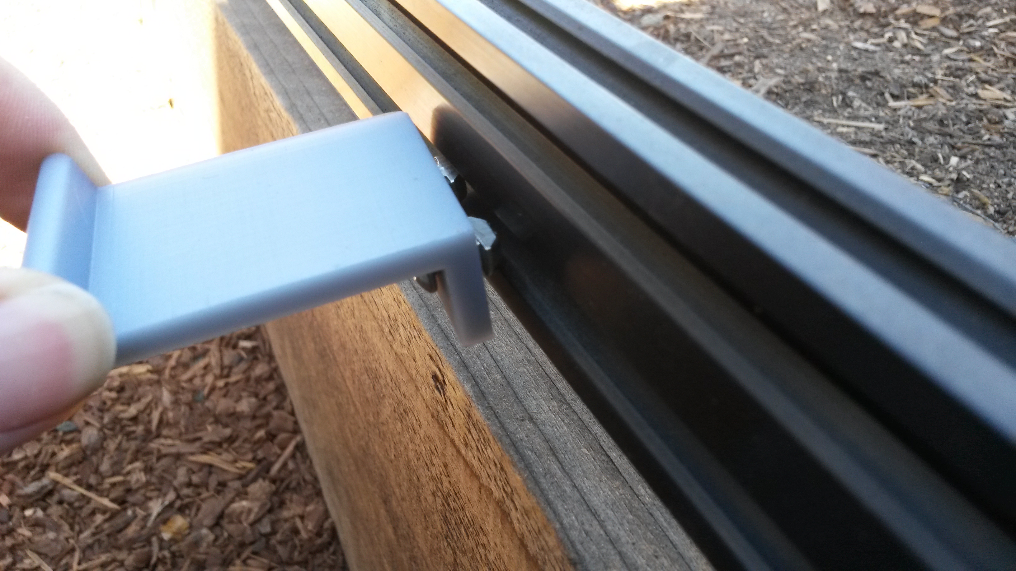

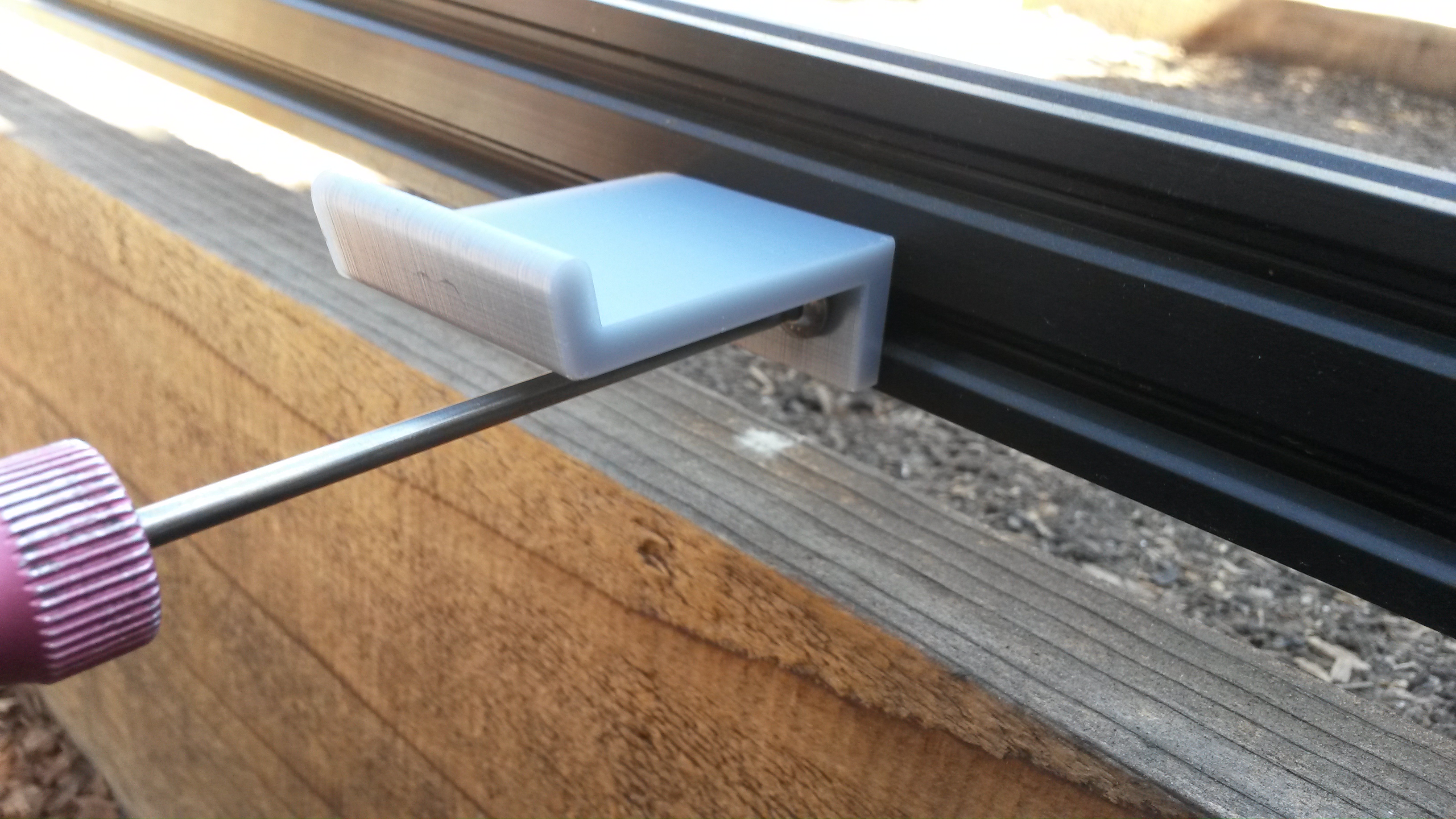
Repeat for all 10 cable carrier supports.
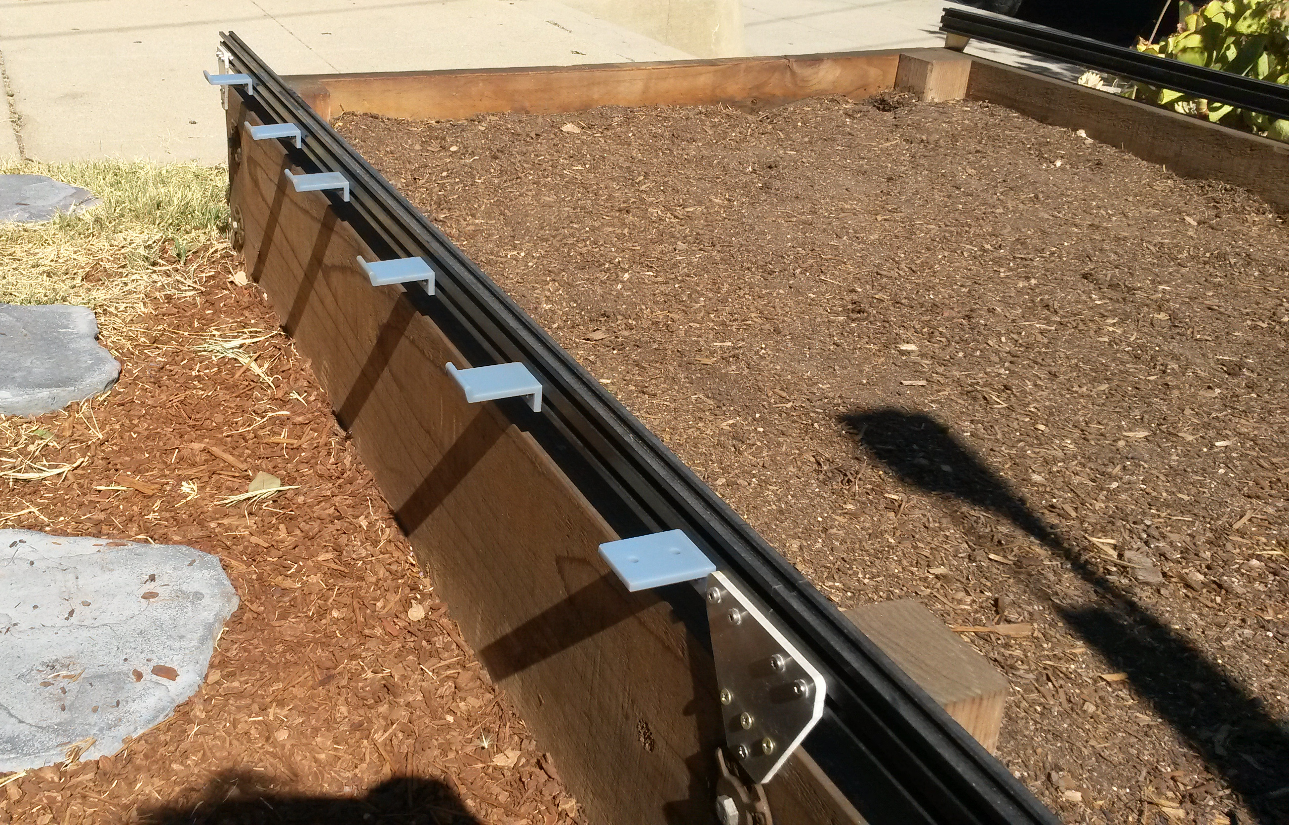
Woo hoo!
You’ve just finished installing your FarmBot’s tracks - arguably one of the most difficult parts of setting up your device.
Onward!