Z-Axis Cable Carrier
- Step 1: Prepare the cable carrier
- Step 2: Orient the cable carrier
- Step 3: Lay out the tube and wiring
- Step 4: Snap in some tabs
- Step 5: Mount the cable carrier to the cross-slide
- Step 6: Mount the cable carrier to the z-axis
- Step 7: Feed the z-axis motor and encoder cables
- Step 8: Add the vertical motor housing
- Step 9: Snap in the remaining tabs
- What’s next?
Step 1: Prepare the cable carrier
Remove all of the snap-in tabs from the z-axis cable carrier. The z-axis cable carrier is the shortest cable carrier in the kit.
Step 2: Orient the cable carrier
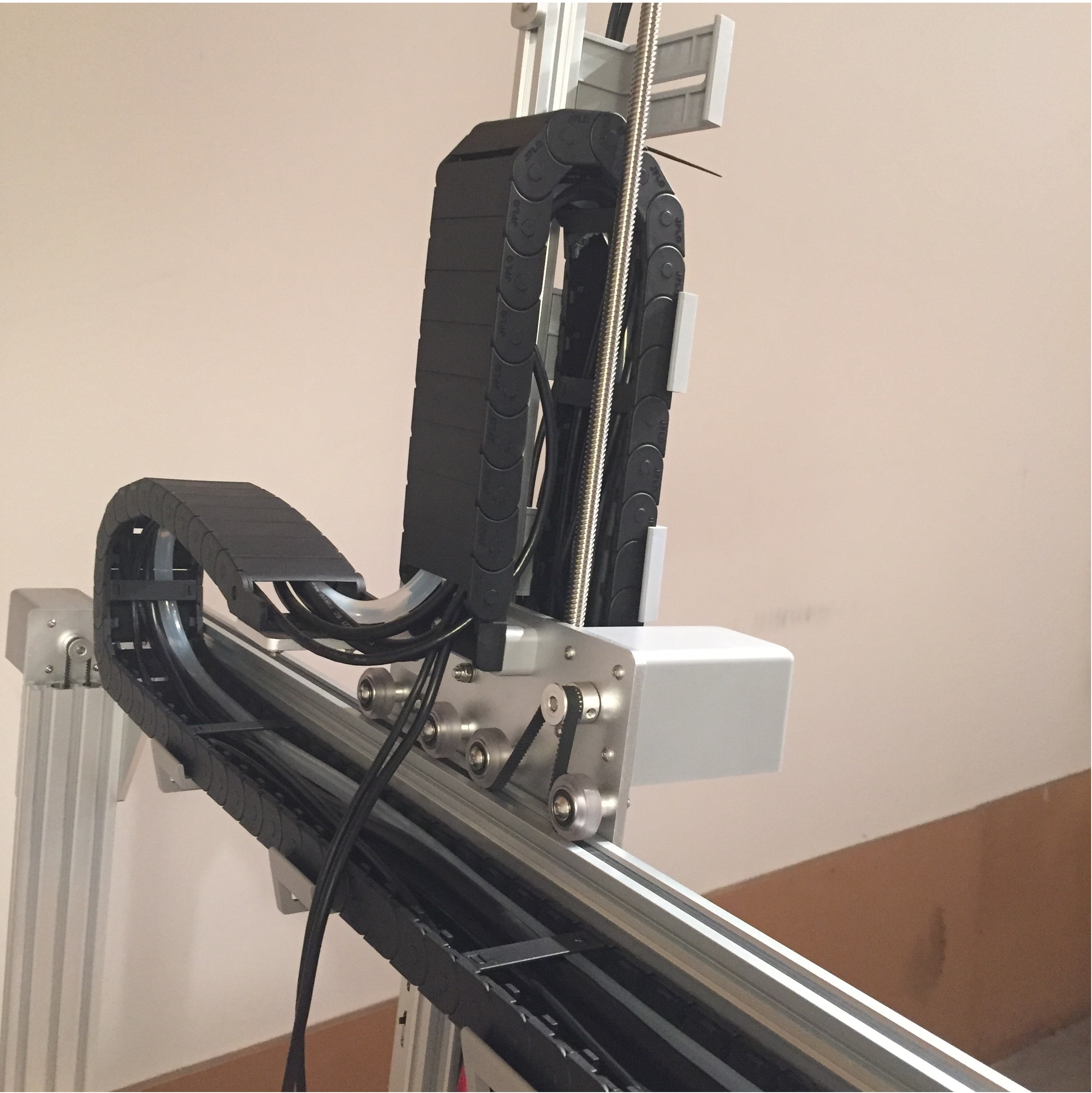
There is only one orientation that the z-axis cable carrier mounts to the cross-slide and z-axis, and it is determined by the orientation of the end pieces. Inspect the images below to see how the cable carrier will be mounted, but do not attach it at this time.
Step 3: Lay out the tube and wiring
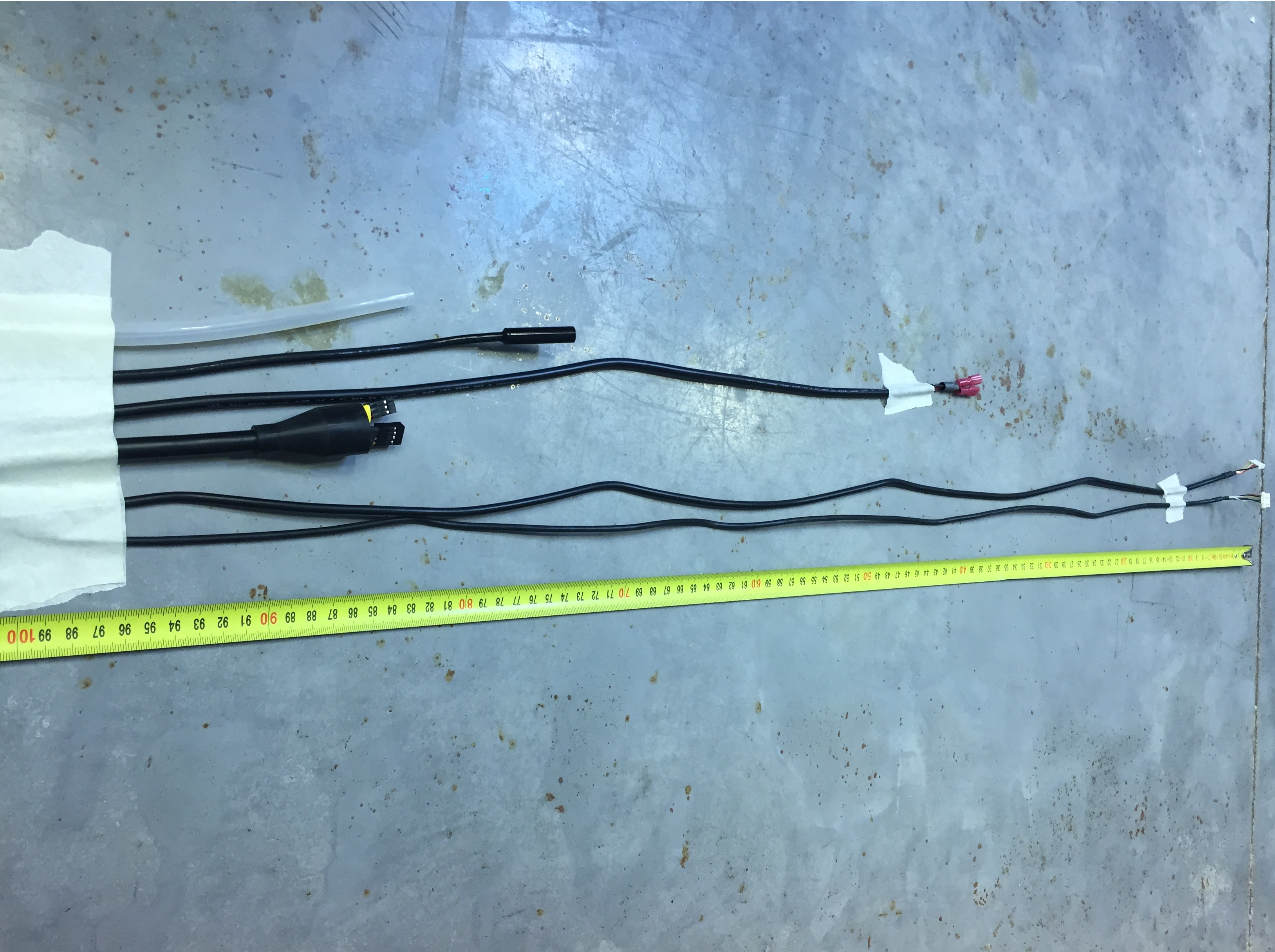
Keeping the mounting orientation of the cable carrier in mind, lay the UTM cable, one of the water tubes, the vacuum pump cable, the camera cable, and the z-axis motor and encoder cables into the open cable carrier. The ends of all cabling and tubing should be offset from the UTM-end of the cable carrier as follows:
- The end of the water tube should extend 10cm beyond the end of the cable carrier.
- The end of the UTM cable with the yellow and black connectors should extend 10cm beyond the end of the cable carrier.
- The end of the camera should extend 15cm beyond the end of the cable carrier.
- The end of the vacuum pump cable should extend 30cm beyond the end of the cable carrier.
- The end of the z-axis motor cable with the white plug that connects to the motor should extend 100cm beyond the end of the cable carrier.
- The end of the z-axis encoder cable with the white plug that connects to the encoder should extend 100cm beyond the end of the cable carrier.
Note: lengths not to scale.

This photo shows what the cables will look like as they are measured out to scale.
Organization is important!
When laying the cables and tube in the carrier, ensure that none of the cables or tube criss-cross over each other. If they do, you will have trouble snapping in the tabs and you risk compressing the tube and preventing water flow.

Z-Axis and Y-Axis Cable Tray Organization
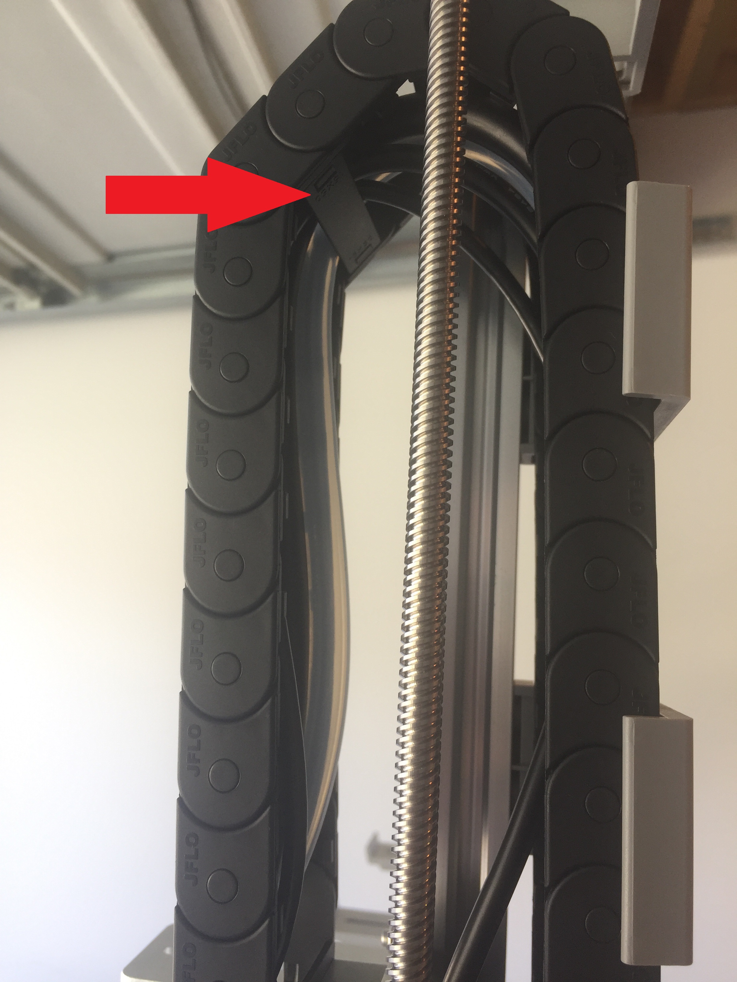
Step 4: Snap in some tabs
Snap in three cable carrier tabs at both ends of the cable carrier, and five more spread throughout the middle of the cable carrier so that as you mount the assembly, the cables and tubing will stay in place. You do not want to snap in all of the tabs at this time because that will make it difficult to adjust any of the tubes or cables if needed.

Snap in some tabs
Step 5: Mount the cable carrier to the cross-slide
Carefully lift the cable carrier assembly and drape it over the cross-slide.
Attach the cable carrier to the cross-slide using two M5 x 30mm screws, M5 washers, M5 locknuts, and the cable carrier spacer block. The screws should thread firmly through the cable carrier end pieces.
Not pictured: The cables and tube coming from the z-axis cable carrier.
Step 6: Mount the cable carrier to the z-axis
Attach the cable carrier to the lowest vertical cable carrier support using two M5 x 16mm screws, M5 washers, M5 locknuts. The screws should thread firmly through the cable carrier end pieces. The mount should be about 125mm from the bottom of the extrusion, but the location can be adjusted as necessary to aid cable installation.
Not pictured: The cables and tube coming from the cable carrier.
Step 7: Feed the z-axis motor and encoder cables
Feed the z-axis motor and encoder cables up through the slots in the vertical cable carrier supports, and then through the slot in the z-axis motor mount. Then connect the cables to the motor and encoder.
Step 8: Add the vertical motor housing
Attach the vertical motor housing to the z-axis extrusion using two M5 x 10mm screws and M5 tee nuts.
Step 9: Snap in the remaining tabs
Once everything is situated well, snap-in the remaining cable carrier tabs, ensuring that you maintain organization of the cables and tube.
Not easy to adjust
Once you snap-in the remaining tabs, it will become impossible to adjust anything without removing the majority of the tabs first. Make sure everything is in place before you make a bunch of extra work for yourself.