Construct the Gantry Structure
Step 1: Attach the plates to the columns
For this part of the assembly you will need:
- The two gantry wheel plate assemblies from the previous page
- The gantry columns (20mm x 60mm x 500mm extrusions)
- 3mm hex driver
Position the gantry column onto the gantry wheel plate assembly. The extrusion should reside on the same side of the plate as the V-wheels and the end of the extrusion should be aligned with the notch in the plate. Tighten the M5 x 10mm screws using the 3mm hex driver.
Handle with care
The aluminum extrusions may have sharp corners and edges.
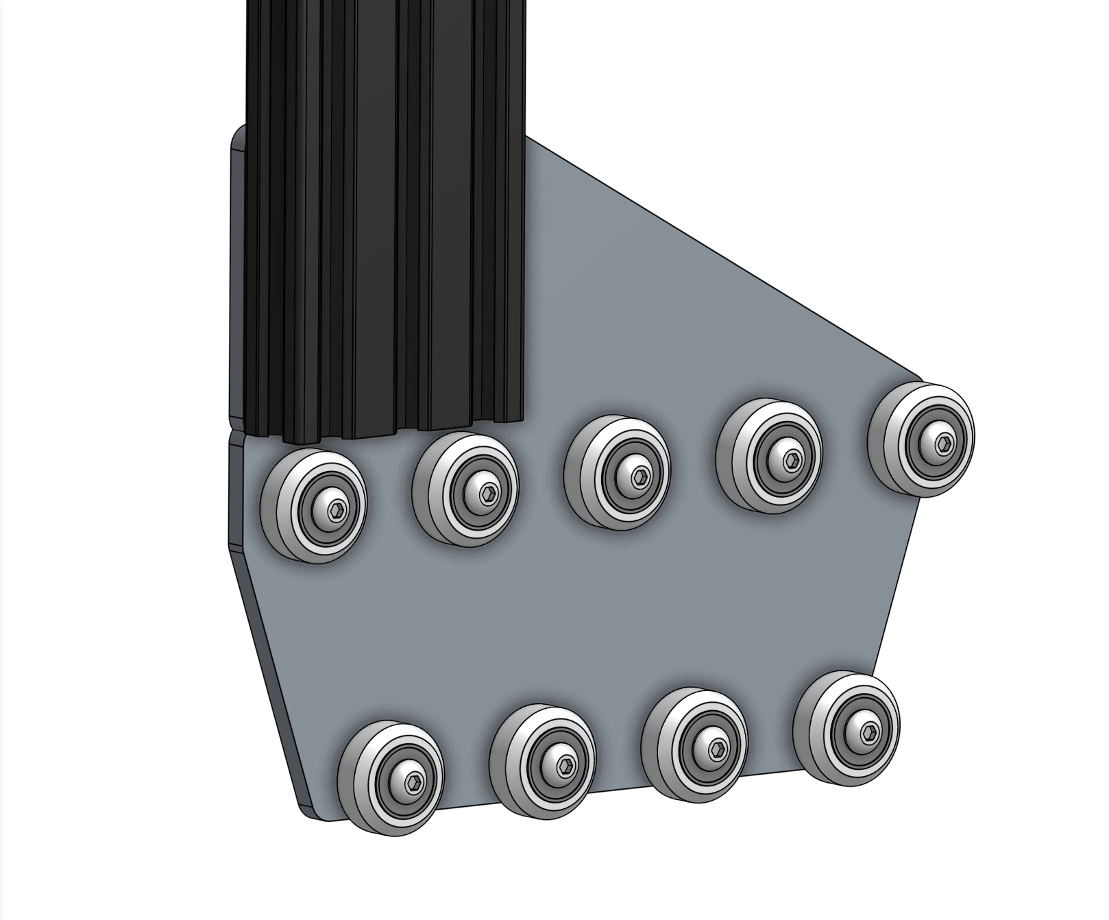
Repeat for the second gantry wheel plate and aluminum extrusion.
Step 2: Attach the gantry corner brackets
For this step you will need:
- The two gantry wheel plate/column assemblies completed in the previous step
- Two gantry corner brackets (one left-hand and one right-hand version)
- 20 M5 x 10mm screws
- 20 M5 tee nuts
- 3mm hex driver
Lightly screw together 10 M5 x 10mm screws and M5 tee nuts on the left-side gantry corner bracket as shown.
Position the corner bracket onto the gantry column/plate assembly. Pay special attention to the orientation of the bracket, extrusion, and wheel plate.
The top of the extrusion should line up with the notch in the corner bracket. Tighten the M5 x 10mm screws with the 3mm hex driver.
Step 3: Repeat
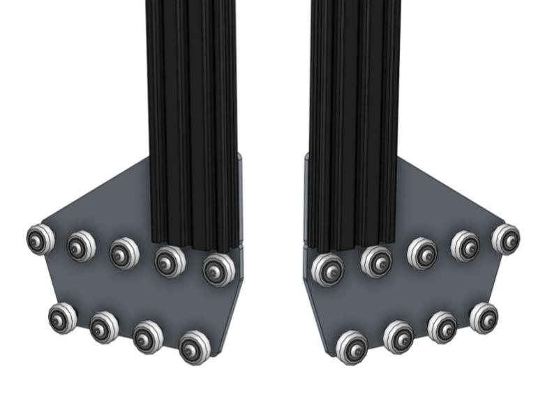
Repeat the above steps for the second corner bracket and column. You should end up with two assemblies that are mirror images of each other. Inspect these images closely to ensure your corner brackets are attached to the columns in the correct orientation.
Step 4: Slide the gantry columns onto the tracks
Adjust the eccentric spacers first
This step is assuming that you have already adjusted the eccentric spacers according to the eccentric spacer adjustment guide.
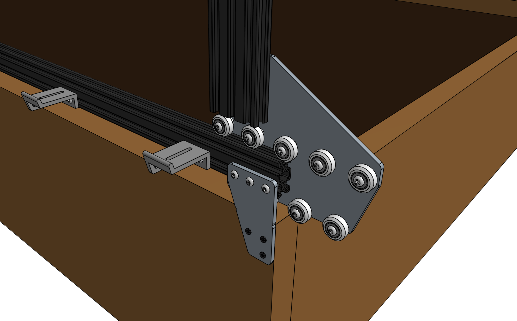
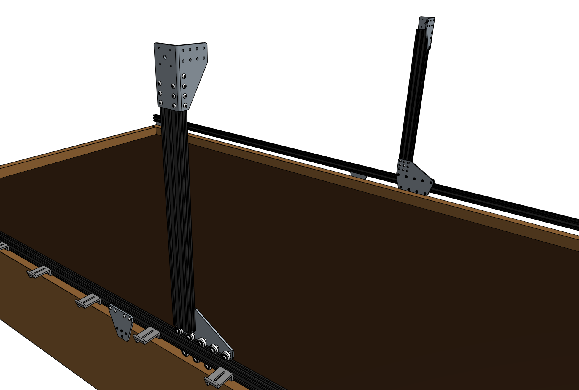
Slide the gantry columns onto the tracks. The direction that the wheel plates extend from the column is towards the front of FarmBot.

Step 5: Assemble the main beam (XL kits only)
This step applies to XL kits only
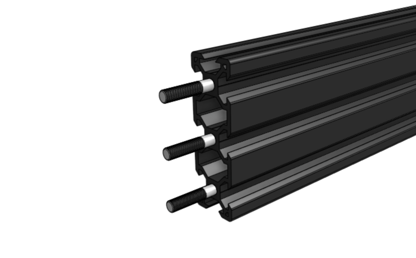
Insert the slightly larger diameter half of three dowel pins half-way into the holes in the gantry main beam. The pins should fit snugly, and require a small amount of force to be put in. If a pin is loose, try inserting it into the second gantry main beam. Be careful to not lose any pins inside the extrusions.
Find a flat surface
The next steps require a flat surface such as a table or patio.
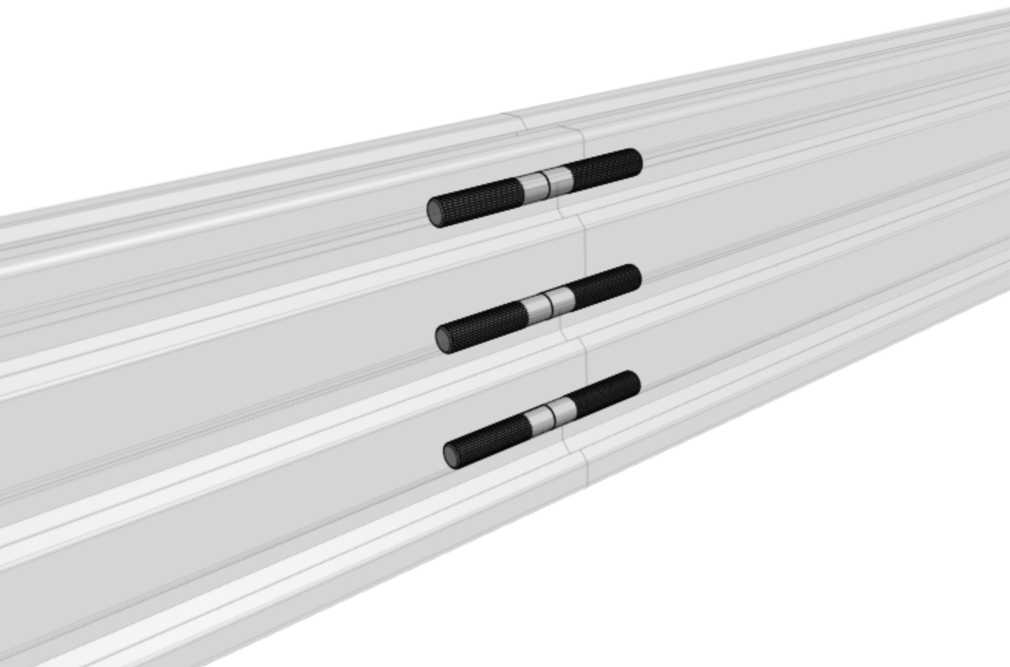
Place both gantry main beams on a flat surface. Then slide the two extrusions together so the exposed dowel pins are inserted into the other beam.
Watch your alignment
At this time the three dowel pins will be keeping the two extrusions aligned. Avoid moving the extrusions in a way that would unalign them, otherwise you risk bending the dowel pins.
Lightly screw 16 M5 x 10mm screws and tee nuts to the gantry joining bracket.
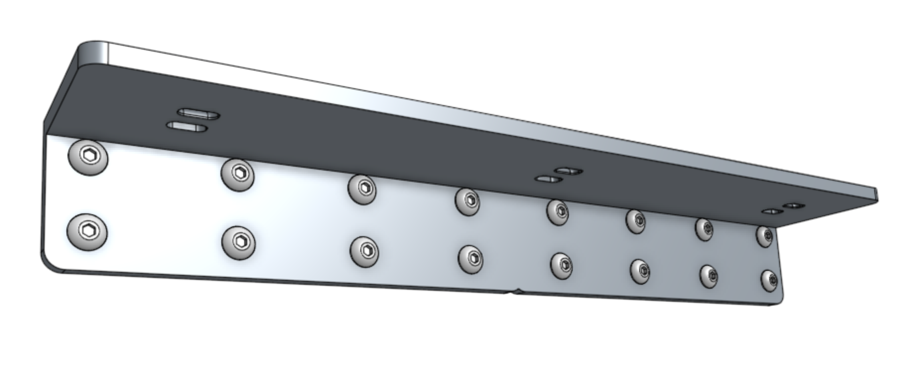
Position the gantry joining bracket onto the lower two slots of the gantry main beam, such that the notch in the middle of the bracket is aligned with the joint of the two extrusions. Then tighten all the screws.
Step 6: Attach the main beam
Insert eight M5 x 10mm screws and M5 tee nuts into the front face of each of the gantry corner brackets. The tee nuts should be facing the front of FarmBot.
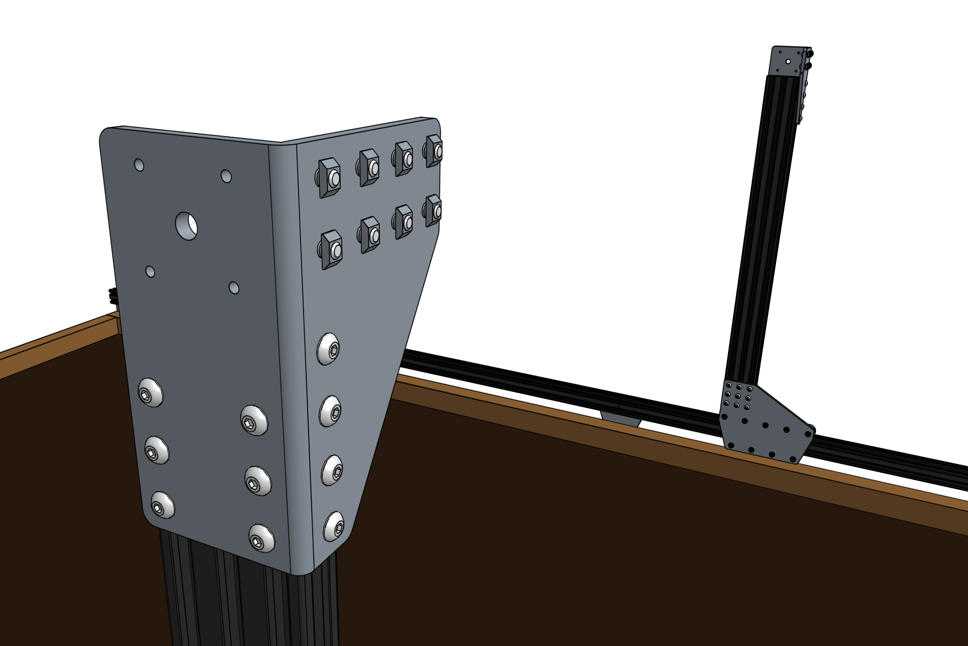
Grab a friend
The next step requires an additional person to complete.
Lift up the gantry main beam and position it onto the front of the gantry corner brackets. The tee nuts should fit into the lower two extrusion slots of the main beam such that the top face of the main beam is 20mm above the top faces of the gantry corner brackets.
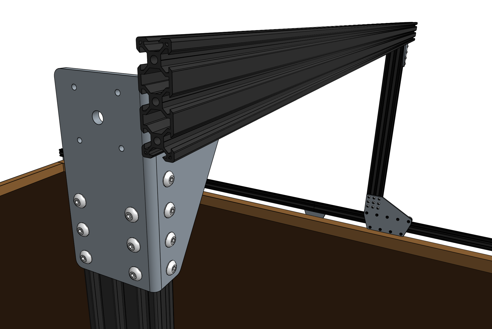

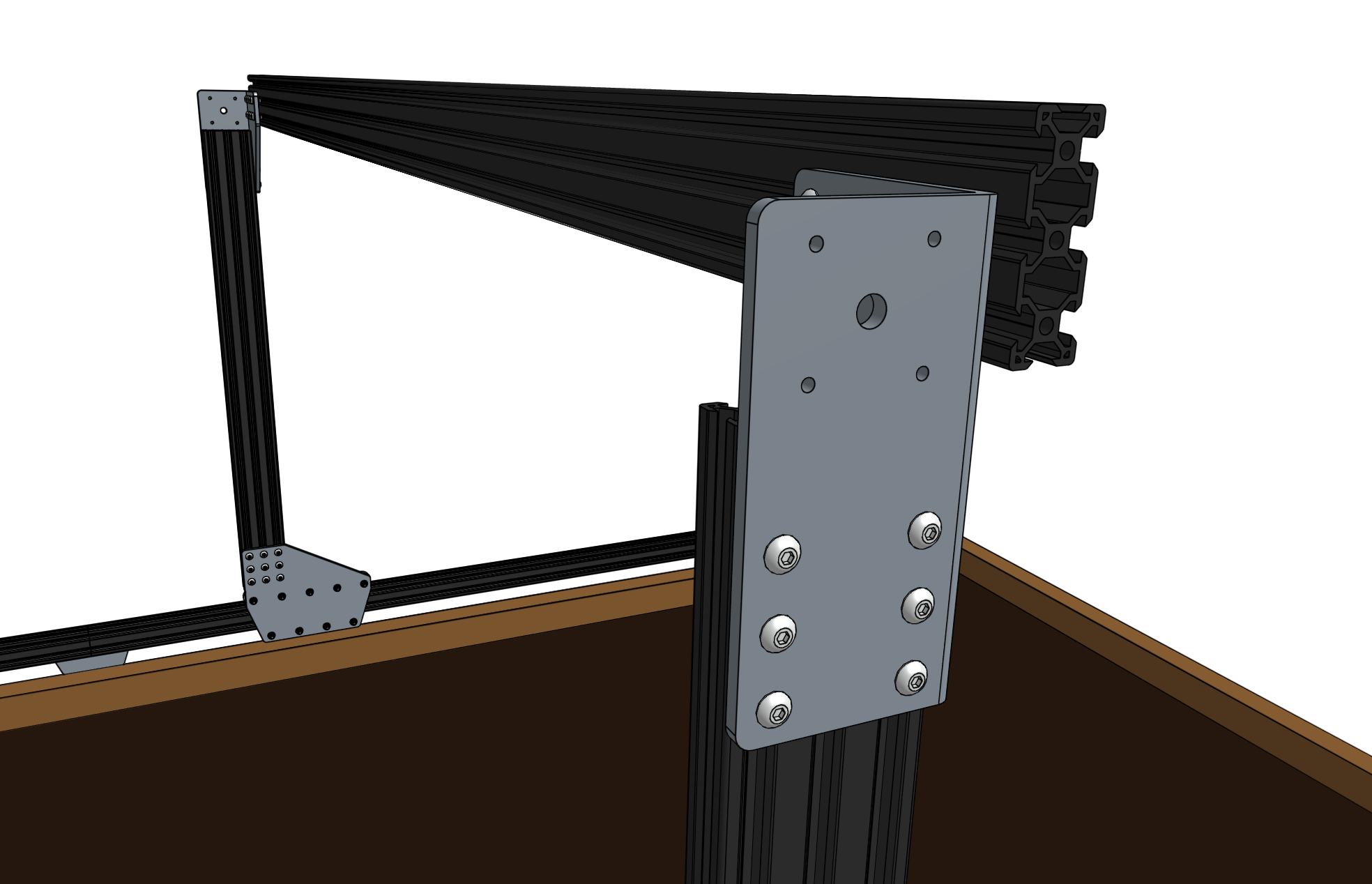
Note that this image is from the backside of FarmBot
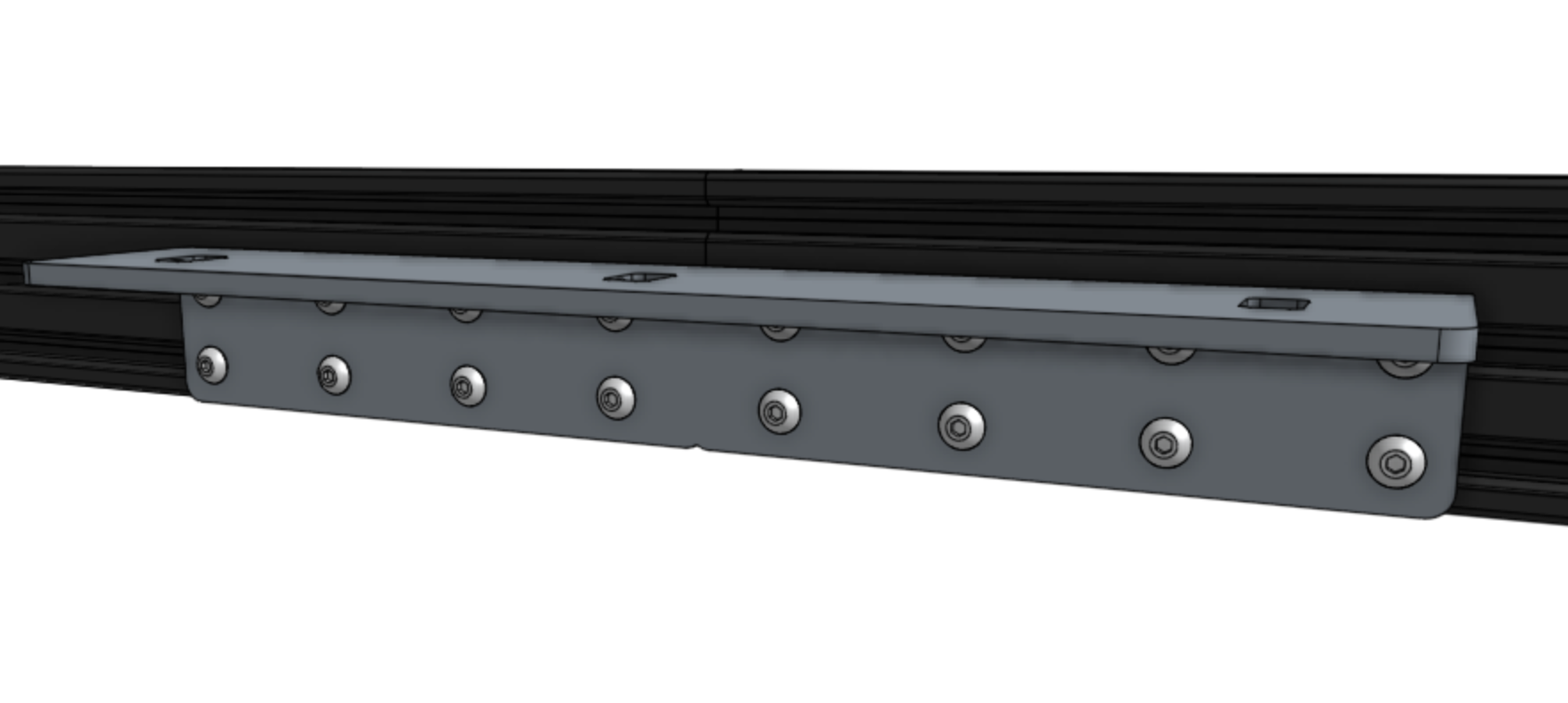
For XL kits, ensure that the gantry joining bracket is on the same side of the main beam as the gantry corner brackets. The top face of the gantry joining bracket should be in the same plane as the top faces of the gantry corner brackets.
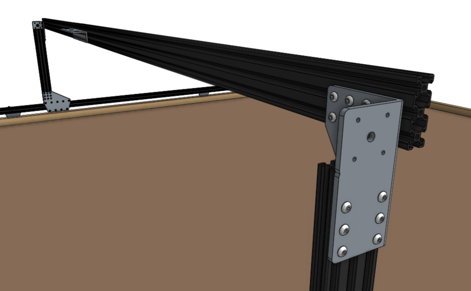
This image is from the backside of a Genesis XL kit, illustrating the position of the gantry joining bracket
Ensure that the gantry columns are vertical and then tighten the 16 M5 x 10mm screws. Depending on the spacing of your tracks, the gantry main beam may extend beyond the corner brackets. This is ok.
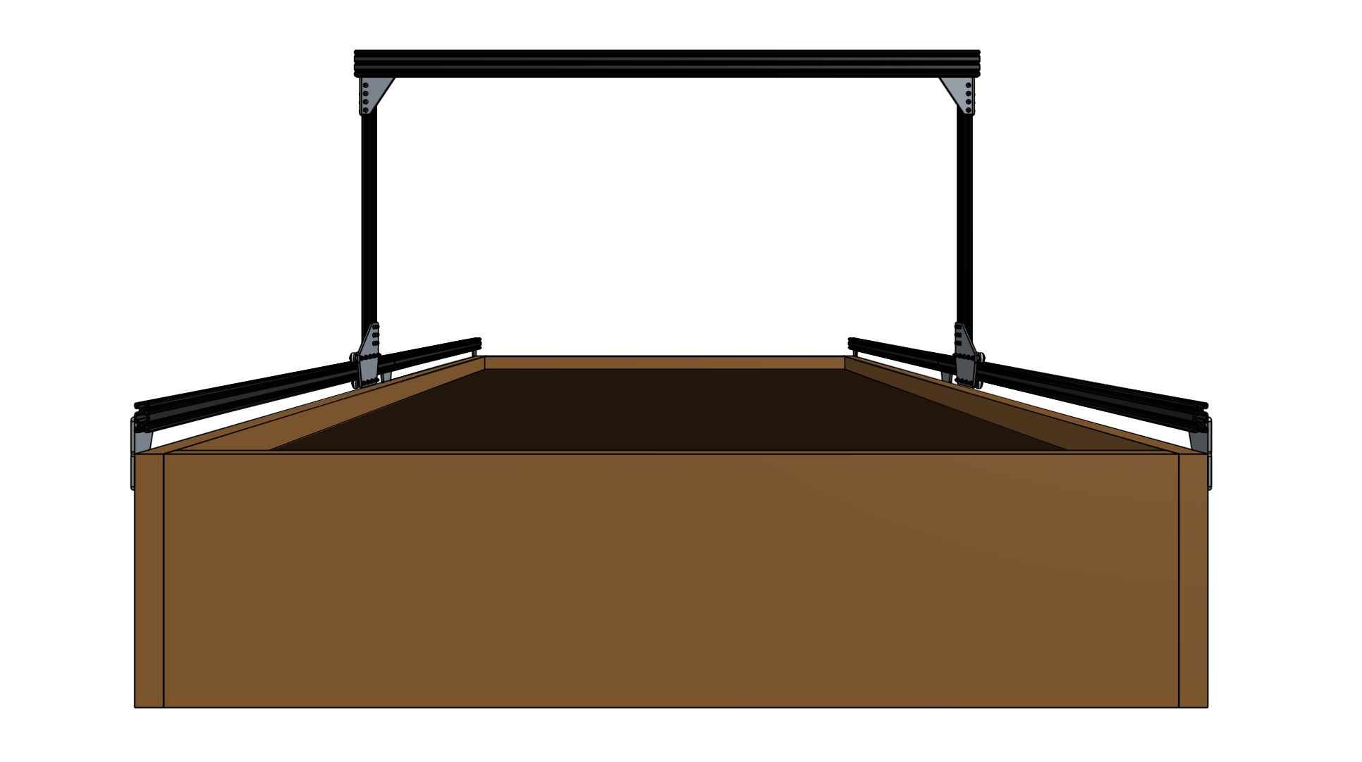
This image is from the front of FarmBot