Electronics
Documentation for FarmBot Genesis electronics
- Component list
- Step 1: Attach the electronics box to the gantry
- Step 2: Attach the cable guides
- Step 3: Connect the peripherals
- Step 4: Plug in the stepper motors and rotary encoders
- Step 5: Plug in the camera
- Step 6: Plug in the UTM cable
- Step 7: Plug the power supply into the Farmduino
- Step 8: Install the heat sinks on the stepper drivers.
- Step 9: Insert the supergland
- Step 10: Install FarmBot OS onto the microSD card
- Step 11: Mount the power supply
- Step 12: Plug in the power supply
- What’s next?
Pre-assembled for your convenience
As of the v1.4 hardware release, the electronics box comes fully pre-assembled. All you need to do is mount it to the gantry column and plug everything in!
Component list
| Qty. | Component |
|---|---|
| 1 | Pre-assembled Electronics Box |
| 6 | M5 x 10mm Screws |
| 6 | M5 Tee Nuts |
| 2 | Cable Guides |
Step 1: Attach the electronics box to the gantry
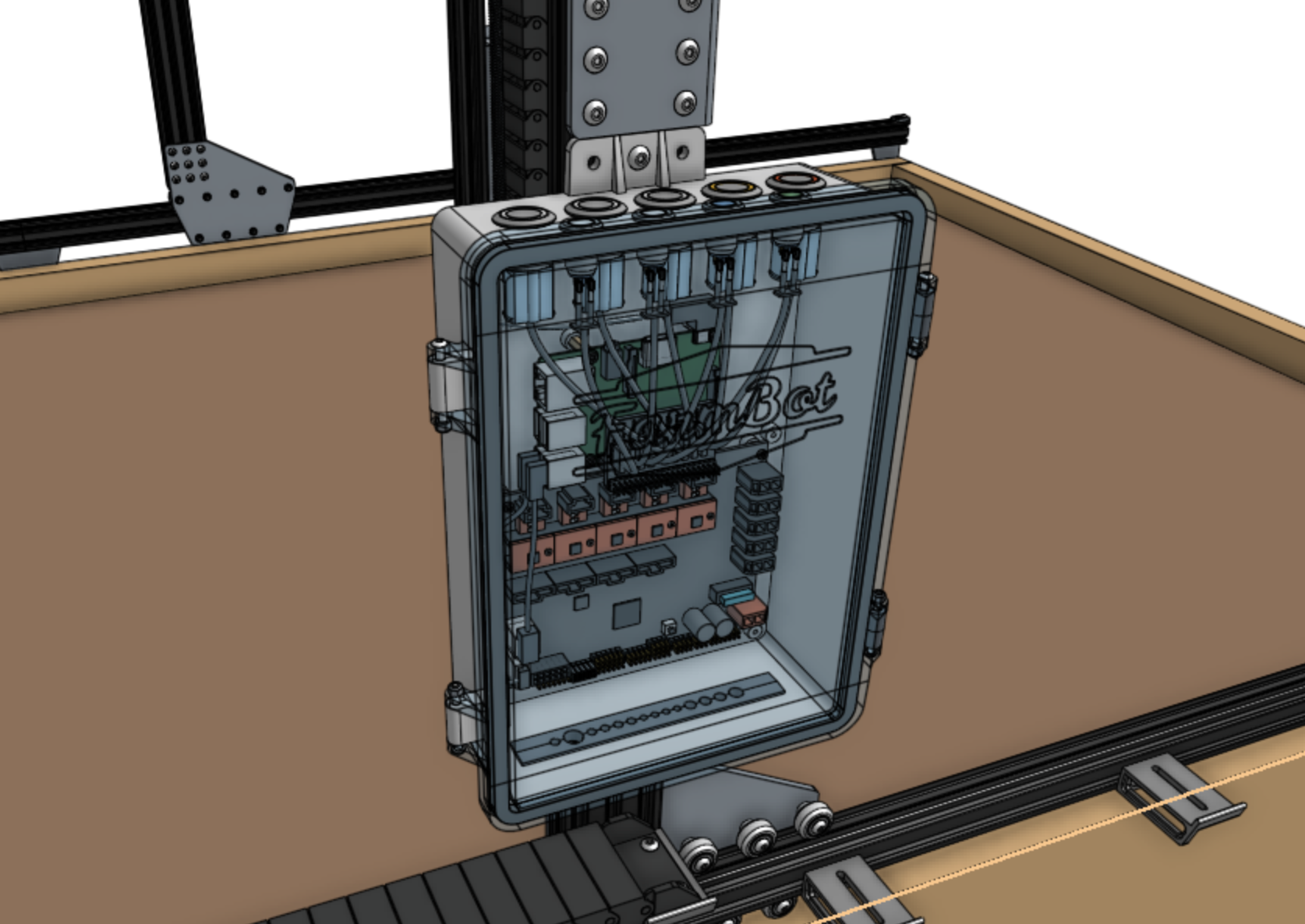
Attach the pre-assembled electronics box to the middle slot on the outside of the left gantry column using two M5 x 10mm screws and tee nuts. The screws should be placed in the middle holes on the top and bottom mounting flanges of the electronics box. The top flange of the box should be butted against the bottom edge of the gantry corner bracket.
Step 2: Attach the cable guides
Attach both cable guides to the back side of the left gantry column using M5 x 10mm screws and tee nuts as shown. Adjust the guides so they secure the motor and encoder cables, UTM cable, LED lights cable, vacuum pump cable, camera cable, and the water tube. Ensure the water tube is not compressed.
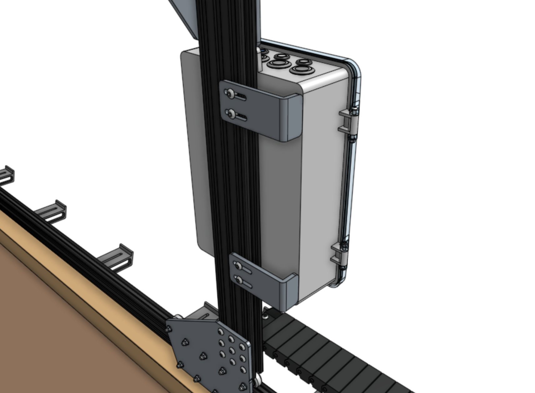
Note: the cables and tubing are not shown in this image.
Step 3: Connect the peripherals
The power supply should still be unplugged at this time.
All cables go through the slot
Before proceeding with plugging everything in, remove the black rubber supergland from the slot in the bottom of the electronics box.
When plugging in cables in the following steps, ensure that you pass every cable through the slot in the bottom of the electronics box. Once everything is connected to the electronics, you will organize all of the cables into the supergland, and then push the supergland back into the slot.
- Connect the LED lights to the Farmduino peripheral connector labelled
LIGHTING(the top right connector on Farmduino). The connector will only fit in one direction. - Connect the solenoid valve cable (with blue heat shrink) to the Farmduino peripheral connector labelled
WATER(directly underneath the lighting connector). The connector will only fit in one direction. - Connect the vacuum pump cable (with gray heat shrink) to the Farmduino peripheral connector labelled
VACUUM(directly underneath the water connector). The connector will only fit in one direction.
The peripheral connectors are highlighted in orange
See Farmduino Peripheral Pin Numbers for information about controlling the peripherals from the web app.
Step 4: Plug in the stepper motors and rotary encoders
Plug in the motor and encoder cables to the Farmduino. Each cable is labelled with a white sleeve, which corresponds to the connectors on the Farmduino. From left to right, the connectors on Farmduino are X1, X2, Y, and Z. Each connector can only be inserted in one direction, and has a locking tab to prevent it from falling out.
The motor and encoder connectors are highlighted in orange
Need to remove a cable?
Each connector has a locking tab which must be pressed in before a cable can be removed from the Farmduino. Be delicate when removing cables, as excessive force could damage the Farmduino.
We recommend slightly pushing the connector away from the locking tab (while you are pressing the locking tab in) to facilitate the tab and connector coming free.
Step 5: Plug in the camera
Plug in the camera to the USB adapter cable.
The USB adapter cable is highlighted in orange
Step 6: Plug in the UTM cable
Plug in the UTM cable to the Farmduino. The connector will only fit in one direction.
The UTM connector is highlighted in orange
Step 7: Plug the power supply into the Farmduino
Connect the red 2-pin power supply connector to the Farmduino’s power input. The connector will only fit in one direction.
The power input connector is highlighted in orange
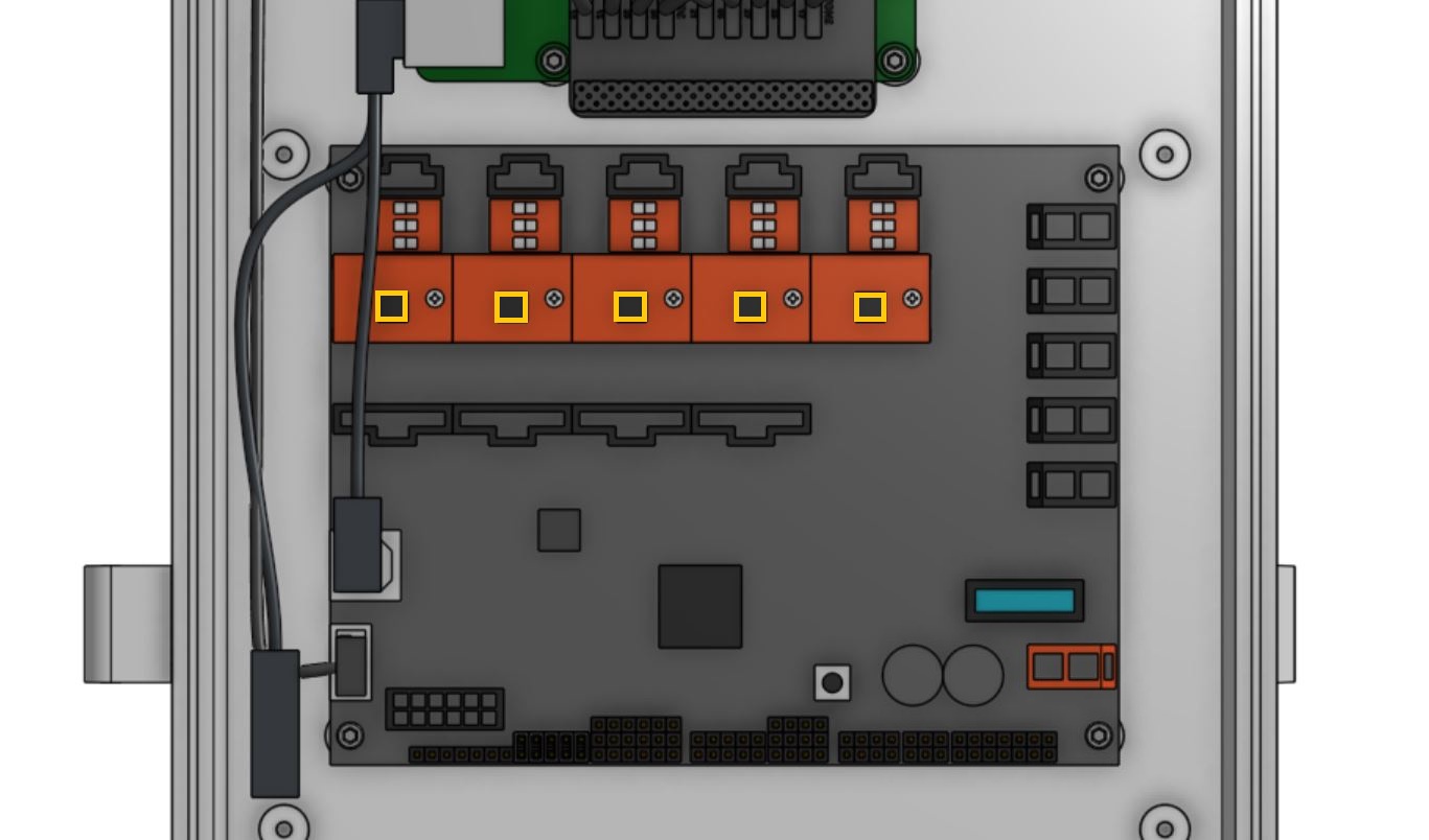
Step 8: Install the heat sinks on the stepper drivers.
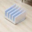
The heat sinks allow for better heat transfer to the air. They are a set of small fins that effectively increase the surface area and allow for better heat rejection. Install the heat sinks in the vertical orientation to take advantage of natural convection.
Only allow the heat sink to contact the stepper driver chip
Do not let the metal heat sink touch any other metal components on the stepper driver. Contact with other components could damage the stepper driver and render it non-functional.
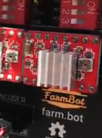
Place the heat sinks squarely and directly on the stepper driver chip in the vertical orientation as shown in the graphic above. The heat sink components will allow the stepper driver chips to remain cool enough to operate in hot environments.
Step 9: Insert the supergland
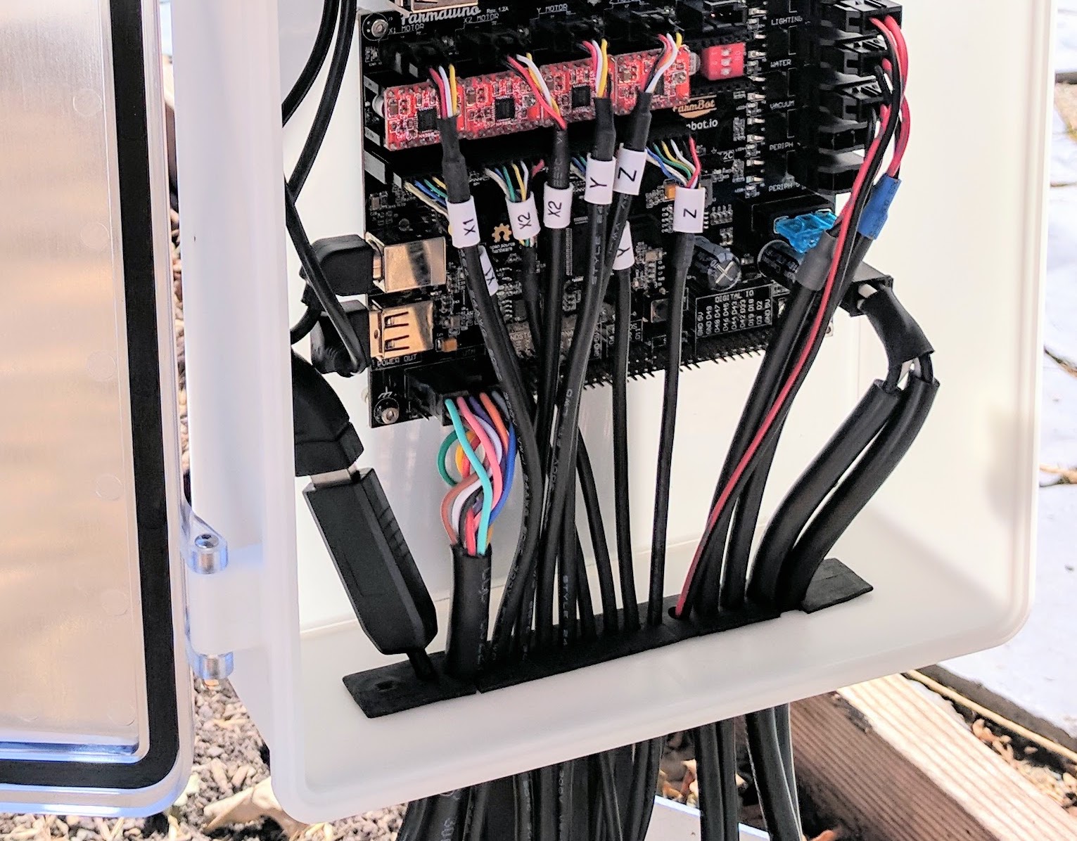
Insert one half of the supergland into the slot in the bottom of the electronics box. The left-most hole in the supergland should be small (it is for the camera) while the right-most hole should be medium-sized (it is for the power supply).
Organize and position the cables into the supergland. From left to right, the cables should be: camera, UTM, motors, encoders, peripherals, power supply.
Once the cables are all inserted into the first supergland half, gently insert the second half of the supergland into the slot in the electronics box. Ensure that the flanges of both supergland halves are on either side of the electronics box wall.
Be gentle
Do not pull any cables away from the electronics box during this process as you could damage a connector or cable.
Step 10: Install FarmBot OS onto the microSD card
Follow these instructions on the software documentation hub to install FarmBot OS onto the microSD card.
Step 11: Mount the power supply
Mount the power supply to your supporting infrastructure using four 25mm wood screws. The power supply is IP67 rated, so it can withstand rain and the elements.
Step 12: Plug in the power supply
Connect the waterproof screw-together 2-pin connector of the power supply cable into the power supply output.
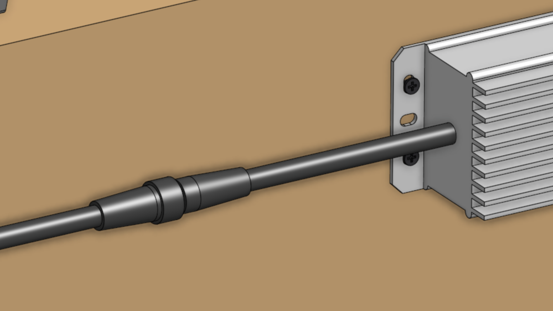
Before plugging the power supply into an outlet or an extension cord, please read the precaution below.
Beware of electrical shock
Remember that once you plug in the power supply, your system will be powered. Once powered, you cannot add, remove, or change any motor cables, peripheral cables, stepper drivers, etc, or you risk frying the electronics and/or being electrically shocked.
If you need to make any changes, you must first unplug the power supply from the wall. This will minimize the risk of electrical shock and the potential to permanently damage your electronics.
If everything looks good, and you understand the precautions needed around powered electronics, go ahead and plug the power supply into a GFCI outlet.
If an appropriate outlet is not close enough to plug in directly, use an extension cord and the provided green outdoor electrical connection protector.
The mark of success
If all has gone well, the Raspberry Pi and Farmduino should boot up and you should revel in the blinking lights!
Smell smoke or heard a loud pop?
If anything seems suspicious or hazardous, immediately unplug the power supply from the wall and contact us at contact@farm.bot.