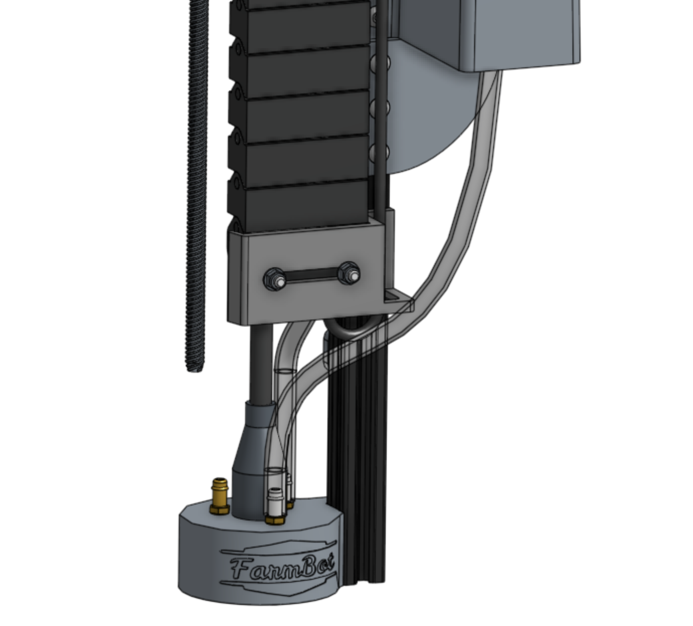
Universal Tool Mount
Documentation and assembly instructions for the FarmBot Genesis universal tool mount
The Universal Tool Mount (UTM) allows FarmBot Genesis to automatically switch tools in order to perform different operations. It is a plastic component that mounts to the z-axis aluminum extrusion using two M5 screws and tee nuts. It features:
- 3 strong neodymium ring magnets to magnetically hold tools in place via other magnets placed in the same configuration on the tool.
- Passageways for water, liquid amendments (eg: fertilizer), and vacuum or compressed air to pass through from the UTM (and the rest of FarmBot) to the tool.
- 12 pogo pins that make electrical connections with tools. (See: Pin Mapping)
Pre-assembled for your convenience
As of the v1.4 hardware release, the UTM comes pre-assembled so all you need to do is mount it and connect the cable and tubes!
Pin mapping
| UTM Pin/UTM Wire | is connected to | and used for |
|---|---|---|
| A /red | +5V | Soil sensor |
| B /yellow | Ground (0V) | Ground |
| C /green | Pin D63 - Digital-In | Tool verification |
| D /black | Pin D59 (A5) - Analog-In | Soil sensor and other analog signal tools |
| E /white | Pin D48 | Anything you want |
| F /brown | Your choice | Anything you want |
| G /blue | Your choice | Anything you want |
| H /grey | Your choice | Anything you want |
| I /orange | Your choice | Anything you want |
| J /purple | Your choice | Anything you want |
| K /pink | Your choice | Anything you want |
| L /cyan | Your choice | Anything you want |
Room for expansion
Only four of the 12 wires/UTM pins are currently mapped. This is because the currently available FarmBot tools only need these four pins to function, which means that the other eight pins are ready for you to map however you desire. Dreaming of a USB, I2C, or PWM based tool? Go right ahead and expand upon your FarmBot’s abilities with custom tools of your own!
Want to make your own UTM compatible tools?
Check out the tool spec to learn how to design and manufacture your own custom tools. We provide examples, CAD models, tech specs, and links to purchase parts.
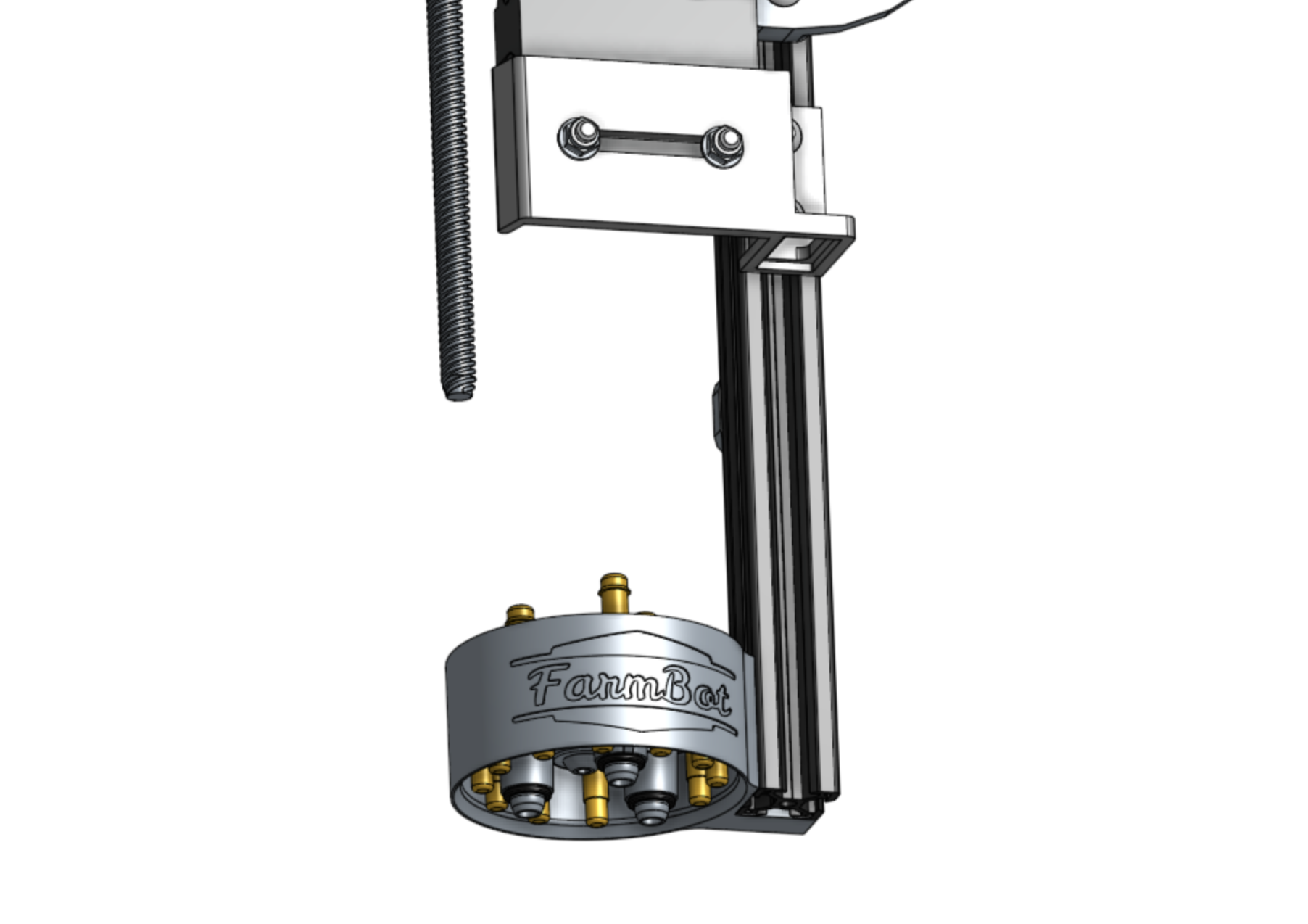
Step 1: Install the UTM onto the Z-axis
Insert two M5 x 16mm screws and tee nuts into the UTM, and then position the UTM onto the z-axis extrusion. The mounting flanges should be positioned on the backside of the extrusion. The bottom of the UTM should be flush with the bottom of the extrusion. Tighten the two screws with the 3mm hex driver.
Step 2: Connect the UTM Cable
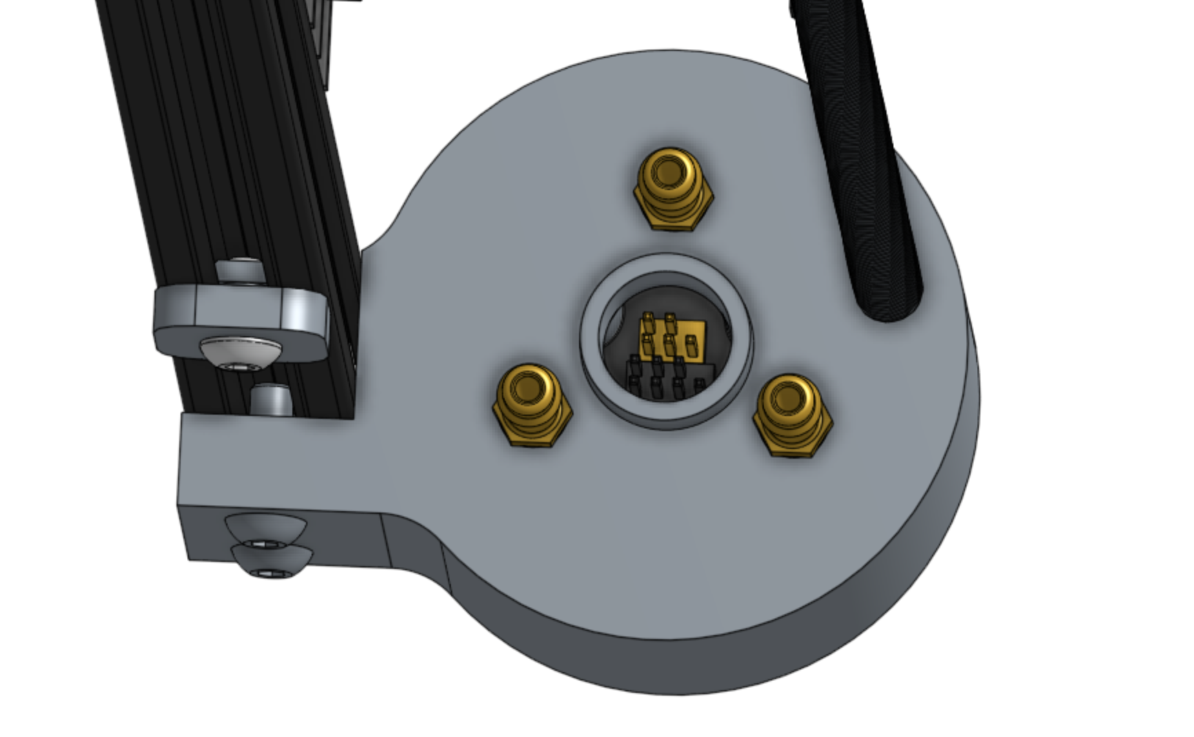
Insert the two UTM Cable Connectors into the top of the UTM. Note: The black and yellow connectors of the cable correspond to the black and yellow pin headers inside the UTM.
Ensure correct connection orientation
Each connector and pin header have one missing pin in the corner to indicate the correct connection orientation.
Look into the UTM to see where the missing pin is located on each pin header. Then look where the individual UTM cable wires enter the connectors to see where the corresponding missing pin is located in the connectors.
Use this information to ensure you insert both connectors in the correct orientation.

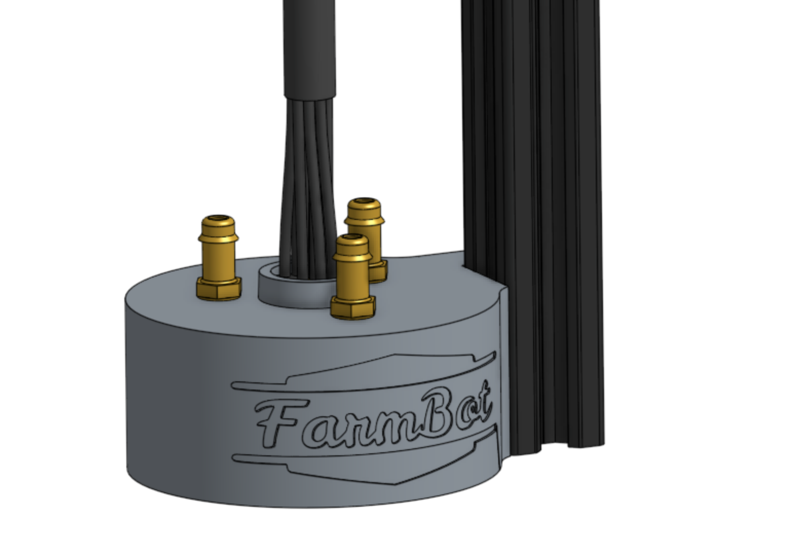
Slide the UTM cable’s shroud down such that it fully covers the opening in the top of the UTM.
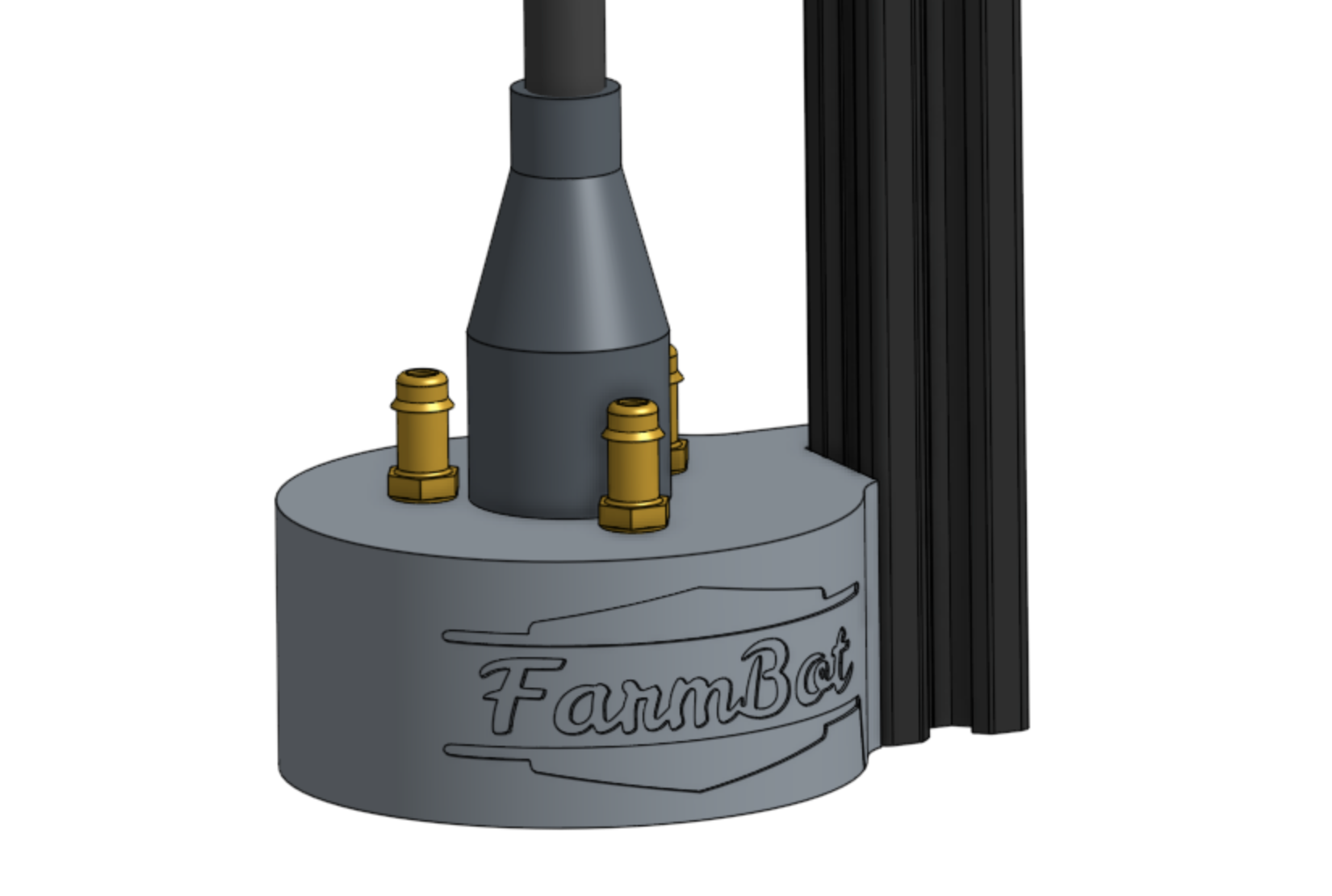
Note: in a few steps from now, you will connect the other end of the cable to the Farmduino.
Step 3: Connect the Water and Vacuum Tubes
Push the water tube onto the barb on top of the UTM that is closest to the z-axis extrusion.
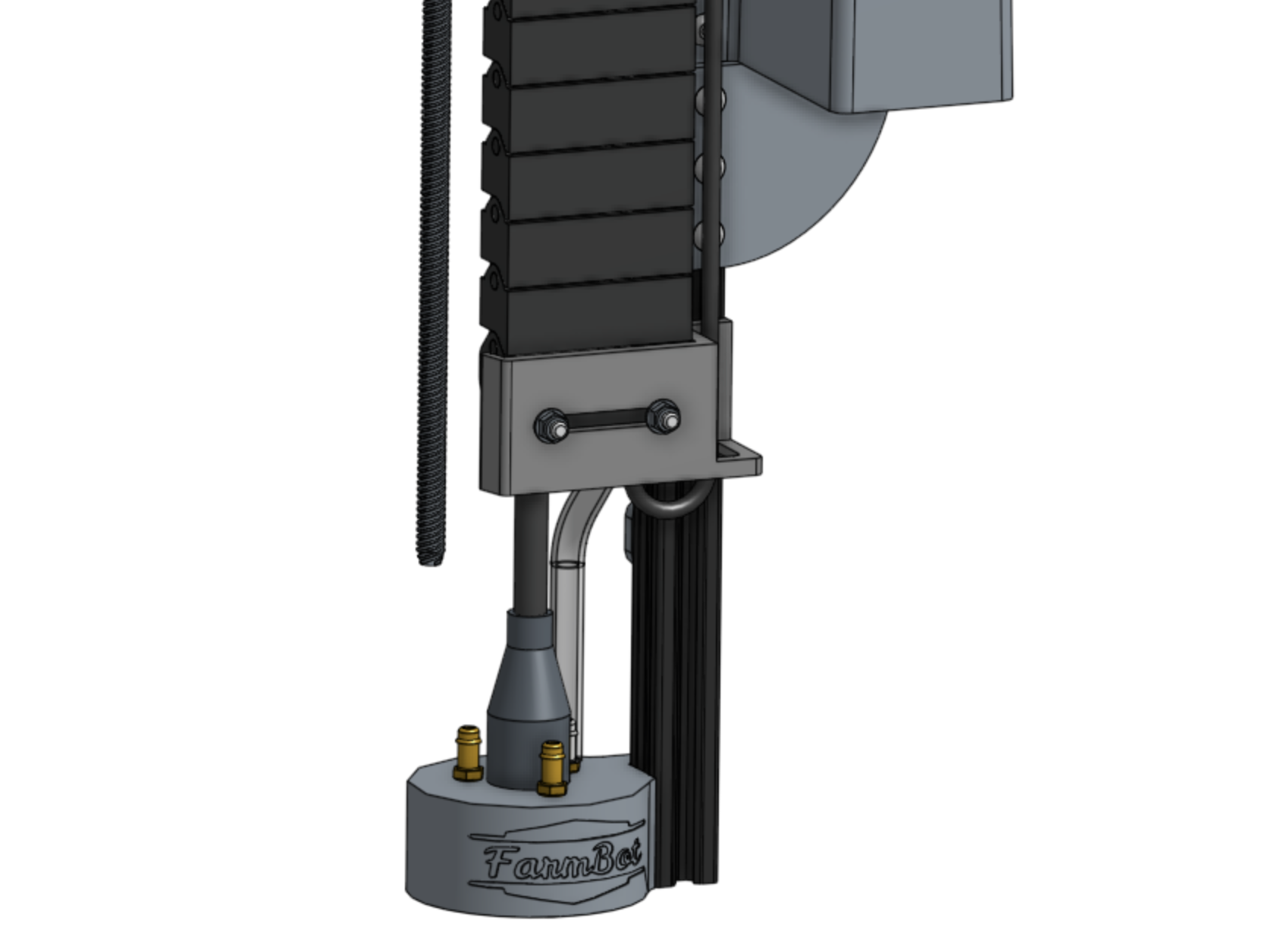
Push the vacuum pump tube onto the barb on top of the UTM that is closest to the FarmBot logo.
