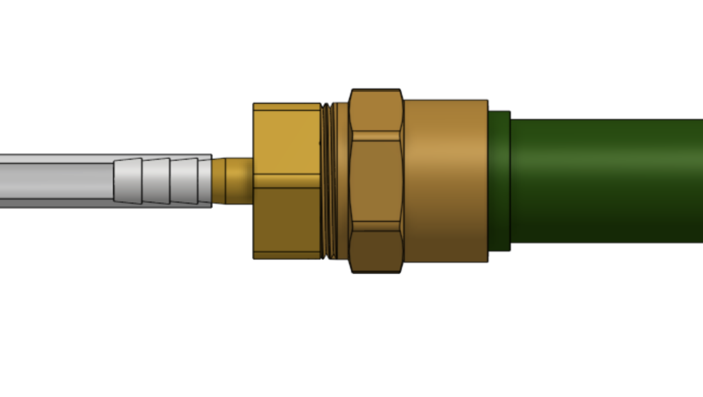
Watering Nozzle
Documentation and assembly instructions for the FarmBot Genesis watering nozzle
- Component list
- Step 1: Assemble the watering nozzle
- Step 2: Install the basic tool hardware
- Step 3: Assemble the solenoid valve and pressure regulator
- Step 4: Mount the solenoid valve and pressure regulator
- Step 5: Wire up the solenoid valve
- Step 6: Connect the tubing
- Step 7: Connect FarmBot to the water source
- What’s next?
The watering nozzle accepts a concentrated stream of water coming from the UTM and turns it into a gentle shower for your plants.
25 minutes
This is the estimated time it will take to assemble the Watering Nozzle
Component list
| Qty. | Component |
|---|---|
| 1 | Watering Nozzle Bottom |
| 1 | Watering Nozzle Top |
| 2 | M3 x 10mm Screws |
| 2 | M3 Locknuts |
| 3 | M5 x 30mm Screws |
| 3 | M5 Washers |
| 3 | M5 Locknuts |
| 3 | Ring Magnets |
| 1 | Jumper Link |
| 1 | Pressure Regulator |
| 1 | Garden Hose (not supplied with FarmBot kits) |
| 1 | Garden Hose Adapter |
| 1 | Solenoid Valve |
| 1 | Barbed Adapter |
| 1 | Coupler |
Step 1: Assemble the watering nozzle
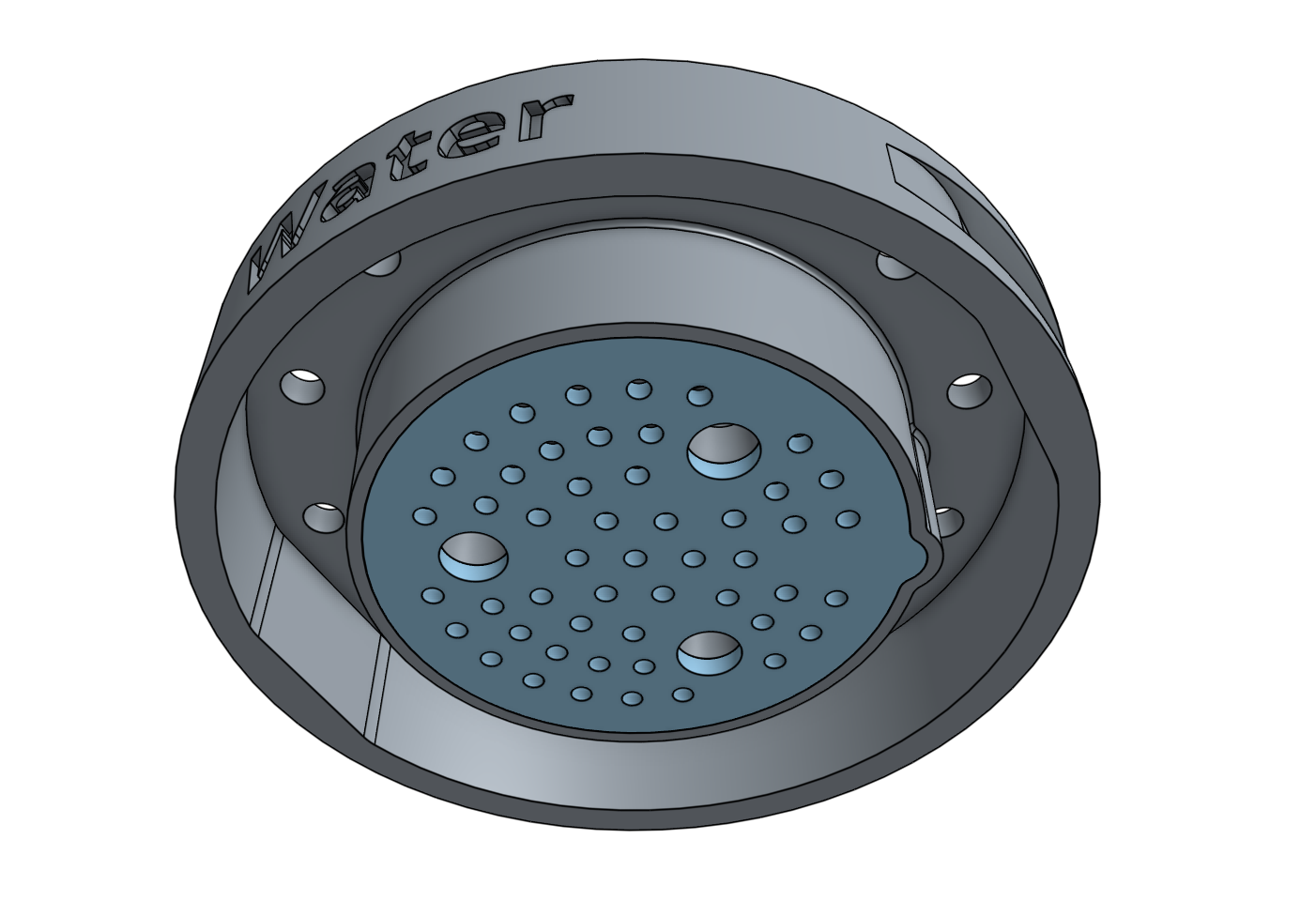
Press the watering nozzle bottom into the watering nozzle top. The two pieces only fit together in one orientation.
Step 2: Install the basic tool hardware
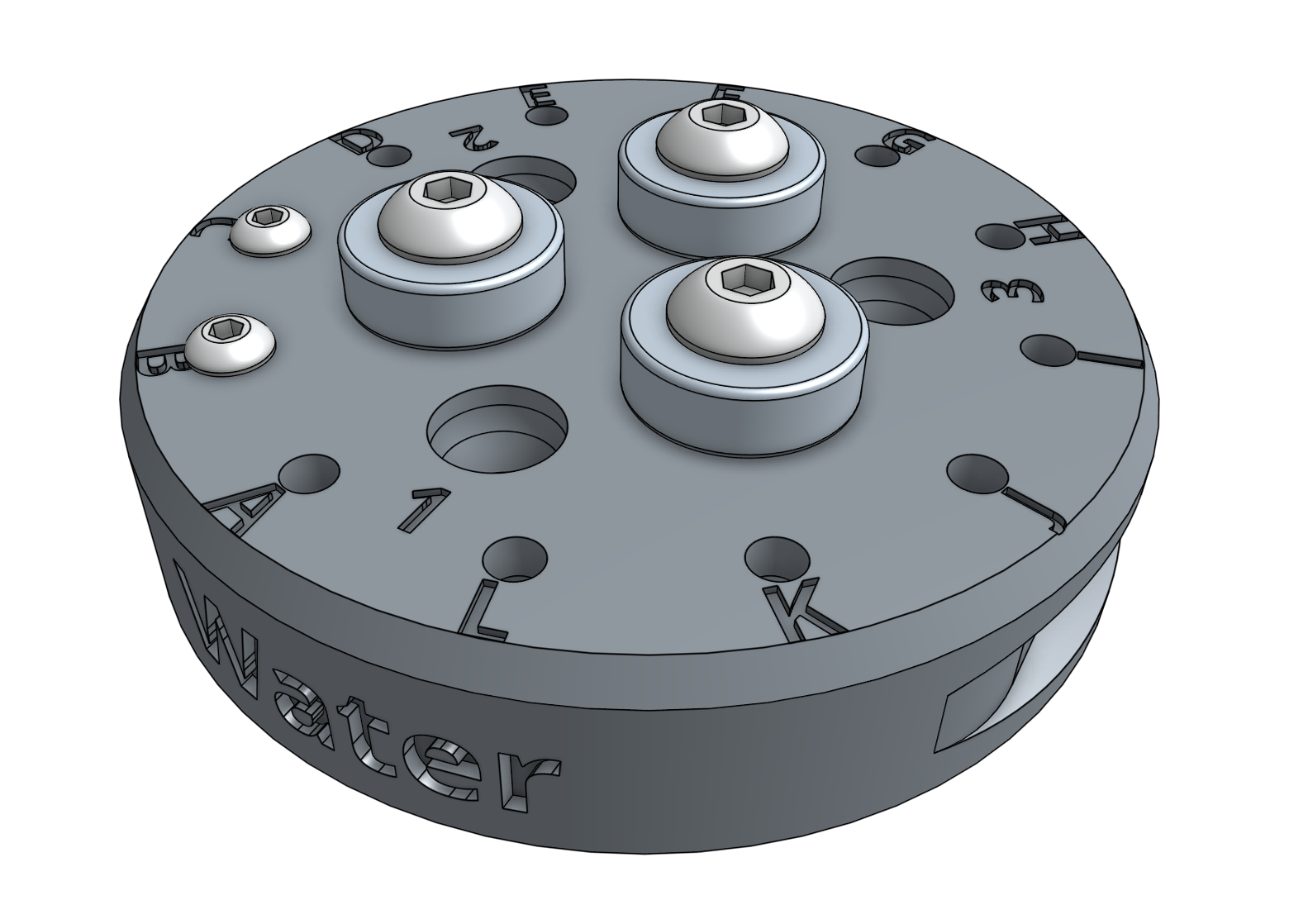
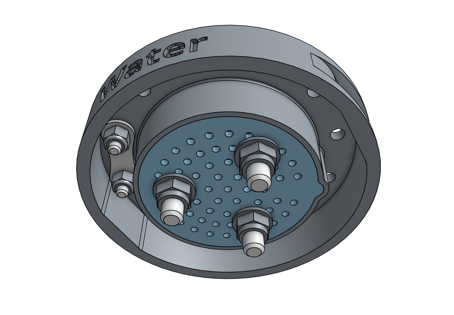
Install the magnets and tool verification jumper link using M5 x 30mm screws and M3 x 10mm screws and the instructions in the basic tool hardware reference guide. The M5 screws will secure the watering nozzle bottom and the watering nozzle top together.

Step 3: Assemble the solenoid valve and pressure regulator
Screw one of the barbed adapters onto the solenoid valve inlet.
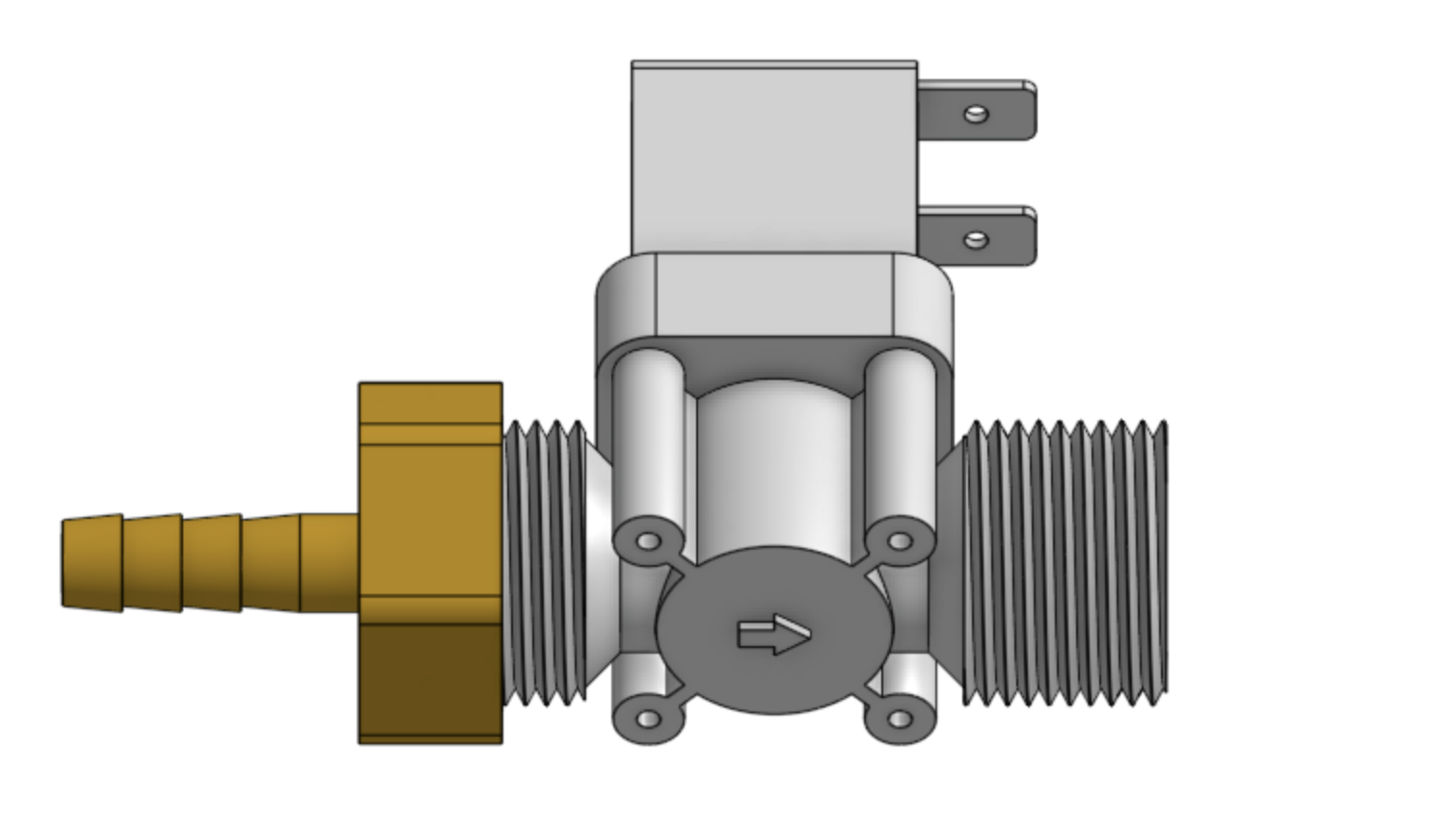
Screw the pressure regulator onto the solenoid valve outlet. Use PTFE tape to seal the threads according to the reference guide.
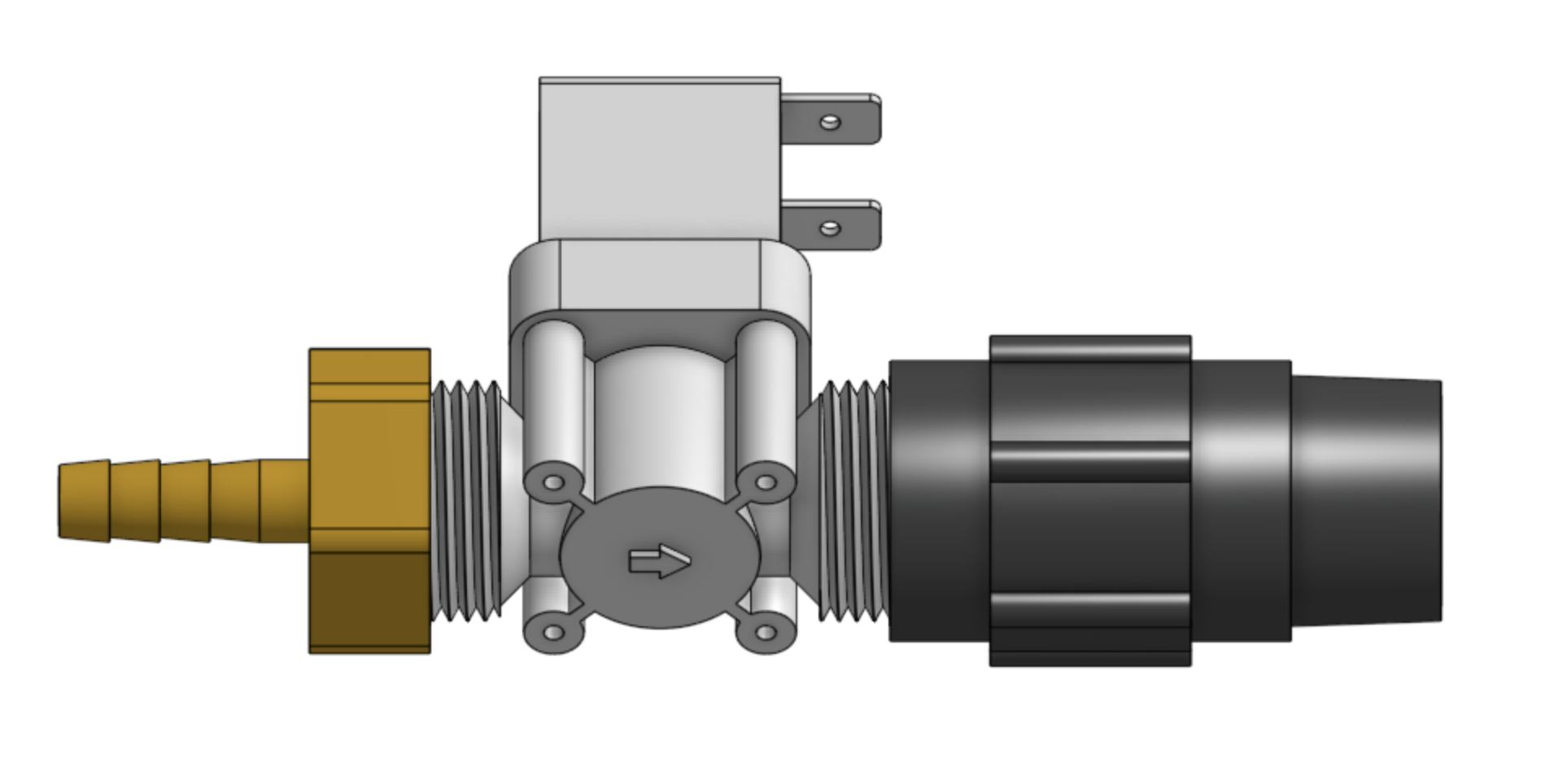
Screw one of the barbed adapters onto the pressure regulator.
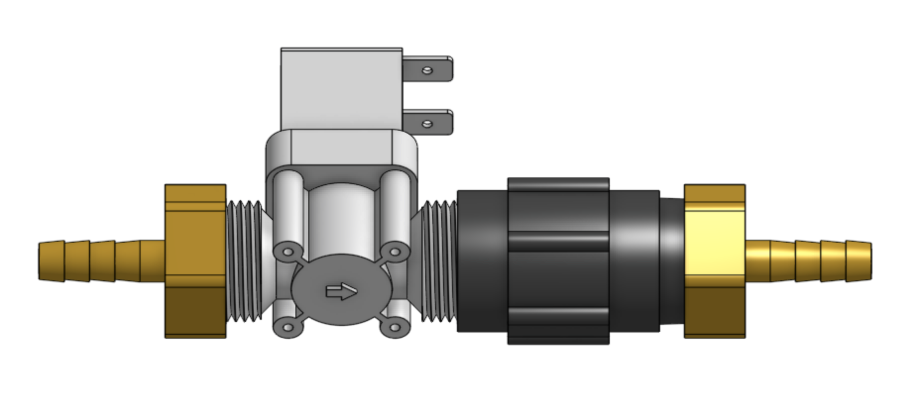
Step 4: Mount the solenoid valve and pressure regulator
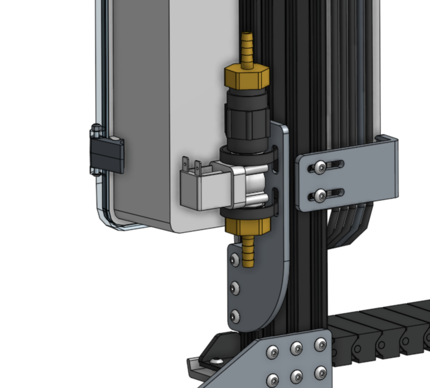
Attach one of the peripheral mount plates to the left gantry column using three M5 x 16mm screws and tee nuts.
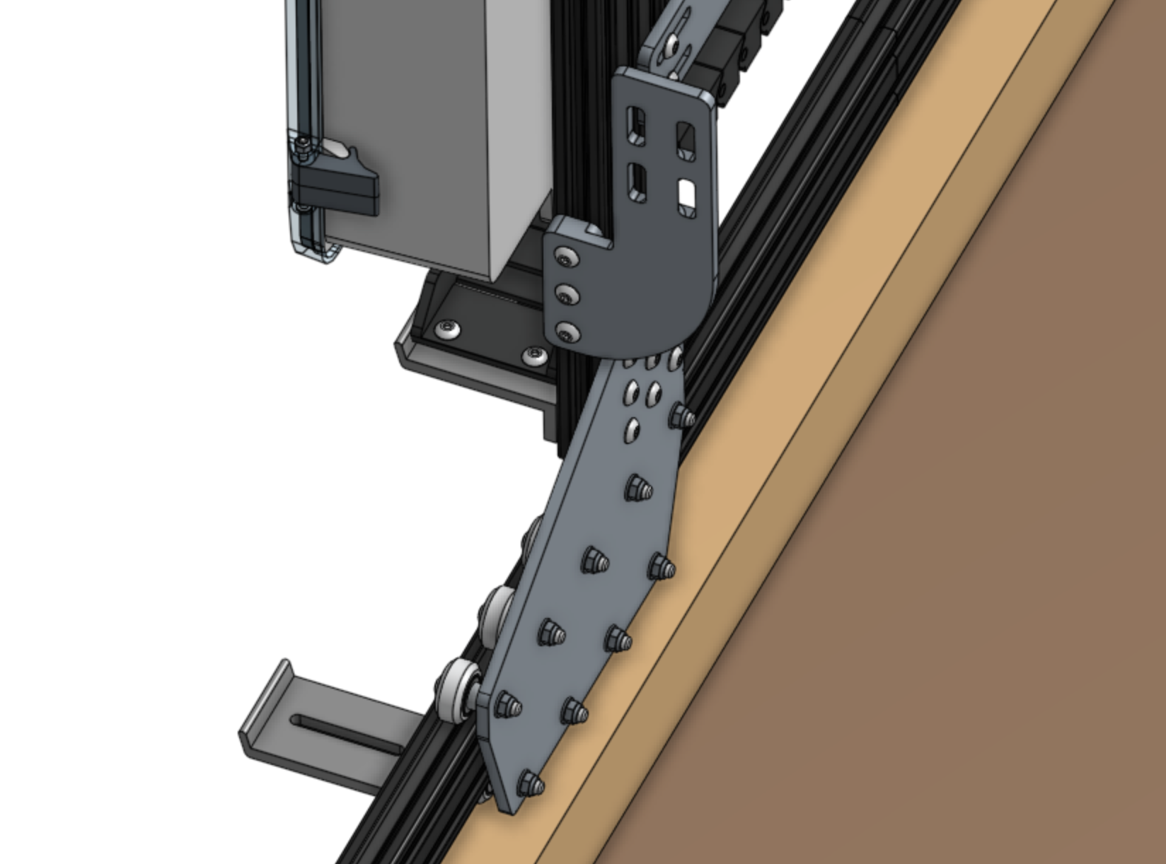
Attach the solenoid valve assembly to the peripheral mount plate using two 200mm zip ties. The pressure regulator should be on top of the solenoid valve when mounted.
Step 5: Wire up the solenoid valve
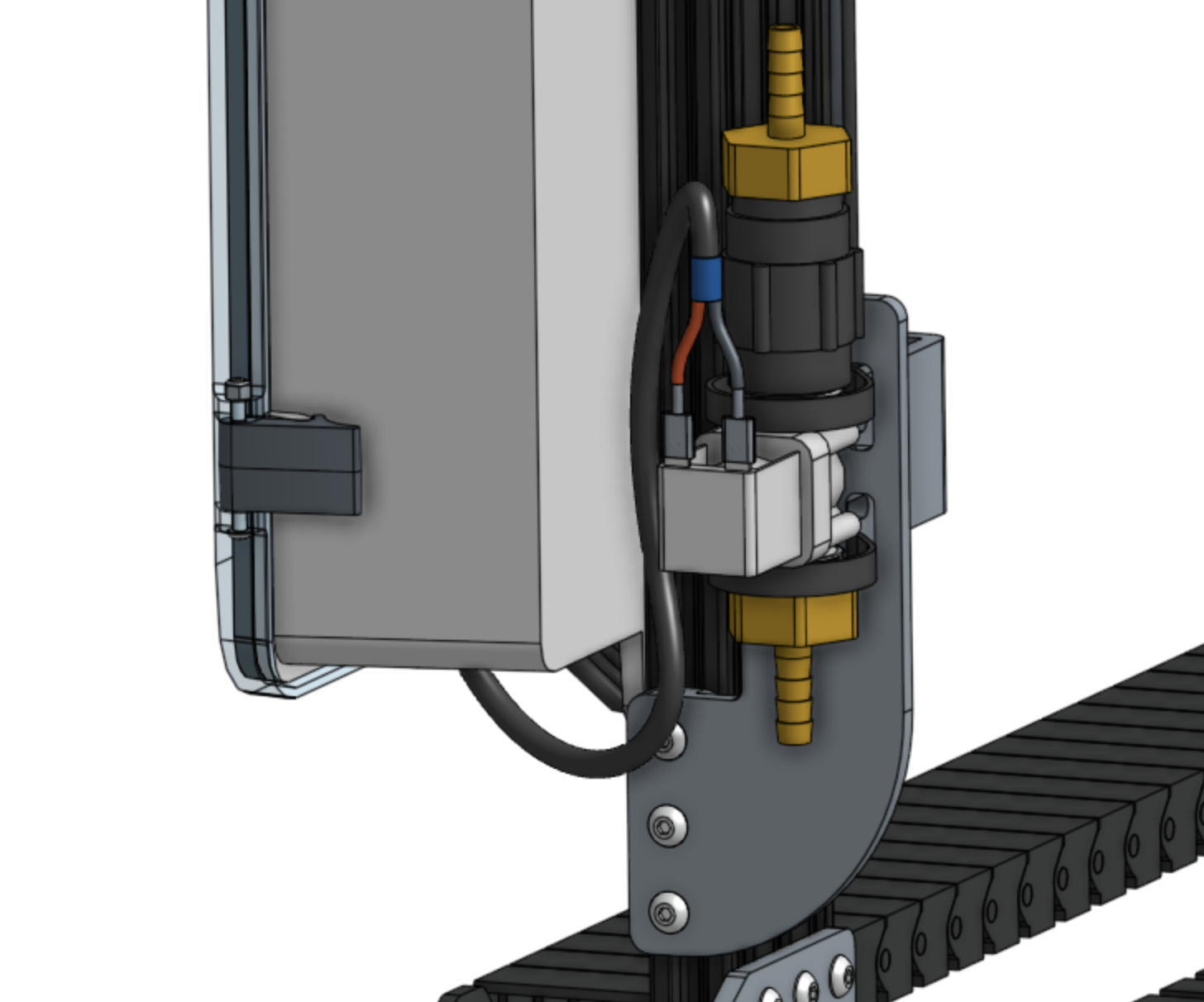
Connect the solenoid valve cable to the solenoid valve’s terminals. Note: in a few steps from now, you will connect the other end of the cable to the Farmduino.
Step 6: Connect the tubing
Push the water tube coming from the y-axis cable carrier onto the top barbed adapter.
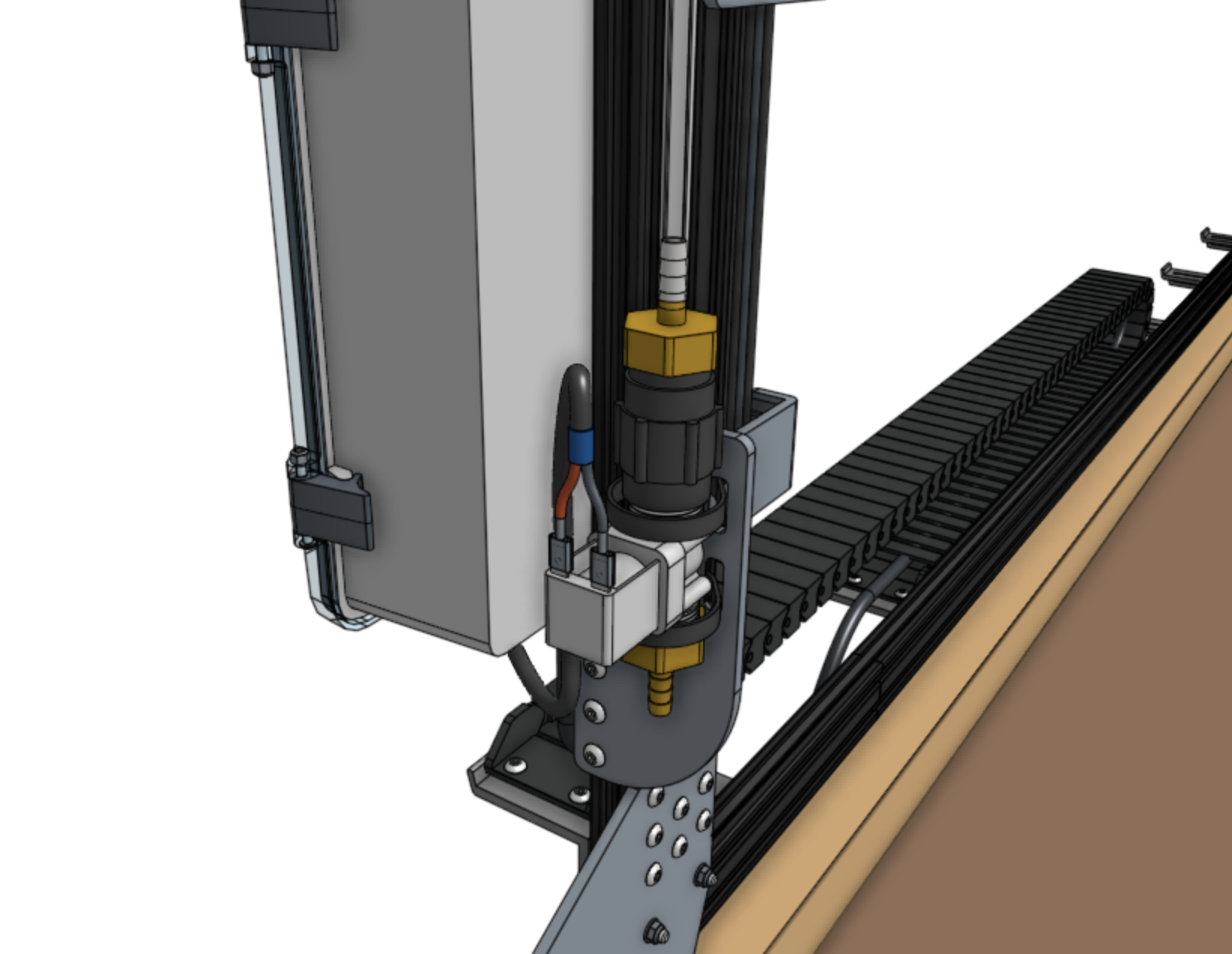
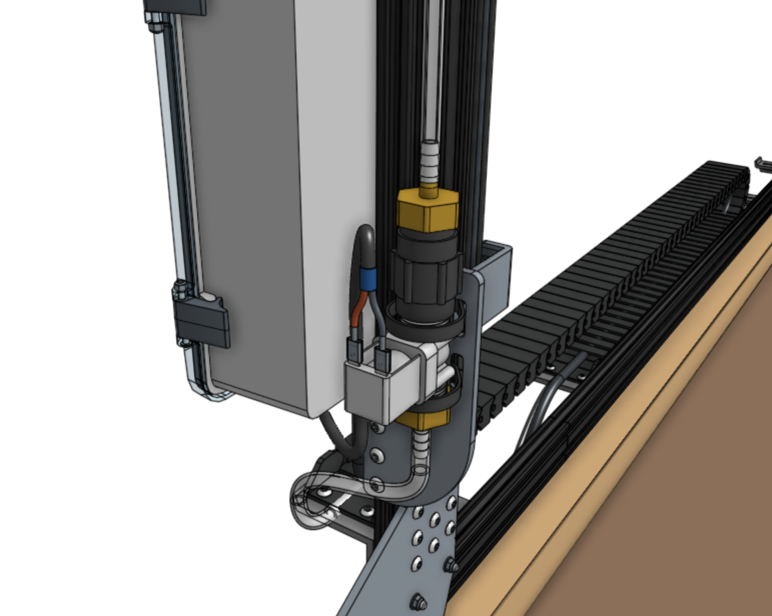
Push the water tube coming from the x-axis cable carrier (where it is mounted to the gantry) onto the bottom barbed adapter.
Step 7: Connect FarmBot to the water source
Screw the garden hose adapter onto the garden hose. Note that you will need to provide a garden hose of the appropriate length to connect FarmBot to your municipal water source - one is not provided with the FarmBot kits.
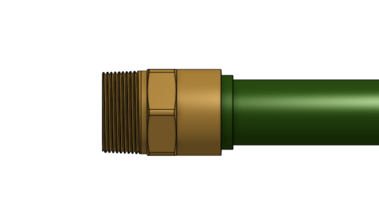
Screw the final barbed adapter onto the garden hose adapter.
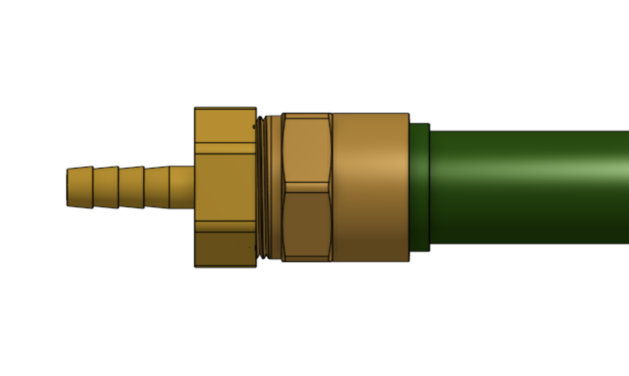
Push the water tube coming from the x-axis cable carrier (where it is mounted to the tracks) onto the barbed adapter connected to the hose.
