Assemble the UTM
45 minutes
This is the estimated time it will take to assemble the Universal Tool Mount.
Step 1: Gather the Parts and Tools
Gather all the UTM parts from the table below and lay them out in a logical manner. To complete the assembly, you will also need the following tools:
- 2mm hex (allen) driver
- 3mm hex (allen) driver
- 6mm wrench
- 8mm wrench
- Exacto blade
- Wire strippers
| Qty. | Component |
|---|---|
| 12 | M3 x 30mm Screws |
| 12 | M3 x 10mm Compression Springs |
| 12 | M3 Locknuts |
| 2 | M5 x 12mm Screws |
| 3 | M5 x 30mm Screws |
| 3 | M5 Washers |
| 2 | M5 Tee Nuts |
| 3 | M5 Locknuts |
| 1 | Universal Tool Mount Base |
| 12 | Zipties |
| 1 | 20 Gauge, 12 Wire Cable, 3m Length |
| 3 | Barbs for 1/4” Tube ID |
| 3 | 1.5mm Wide, 9mm ID Square-Profile O-Rings |
| 3 | 15 x 5 x 5mm Ring Magnets |
Step 2: Install the magnets
Opposites attract
For the UTM to correctly mount tools, all magnets on the UTM and all tools must have the same polar orientation. For example, all of the magnets could have the North pole/face of the magnet facing towards the ground. This way, the North pole/face of the UTM magnets (which face the ground) will be attracted to the South pole/face of the tool magnets (which face the sky).
Which side is North and which is South does not matter. The important part is that the orientation of all the magnets are the same.
Insert an M5 x 30mm screw through one of the ring magnets. For the first magnet, the orientation does not matter.
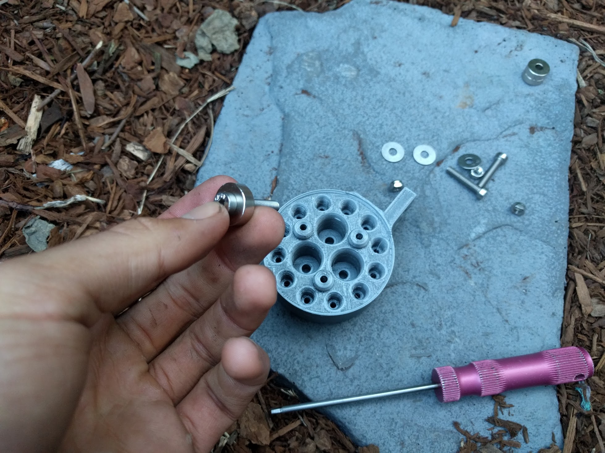

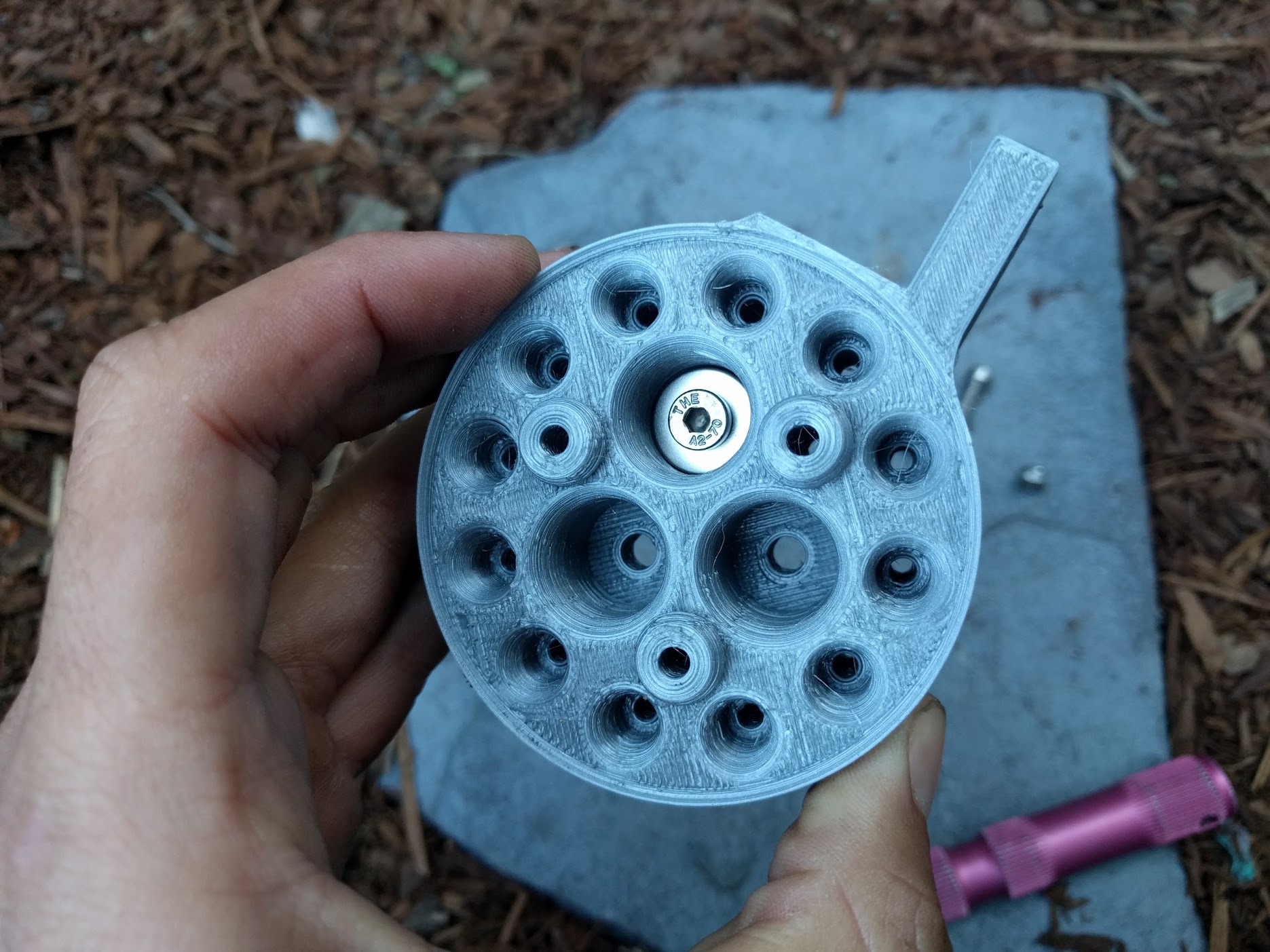
Insert the magnet/screw combo into the UTM and use the 3mm hex driver and the 8mm wrench to tighten an M5 locknut and M5 washer onto the screw.
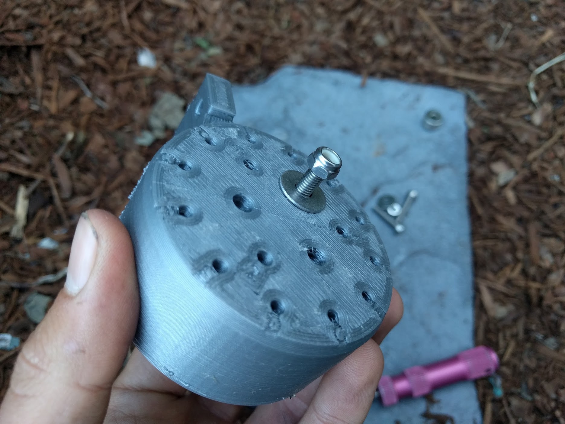

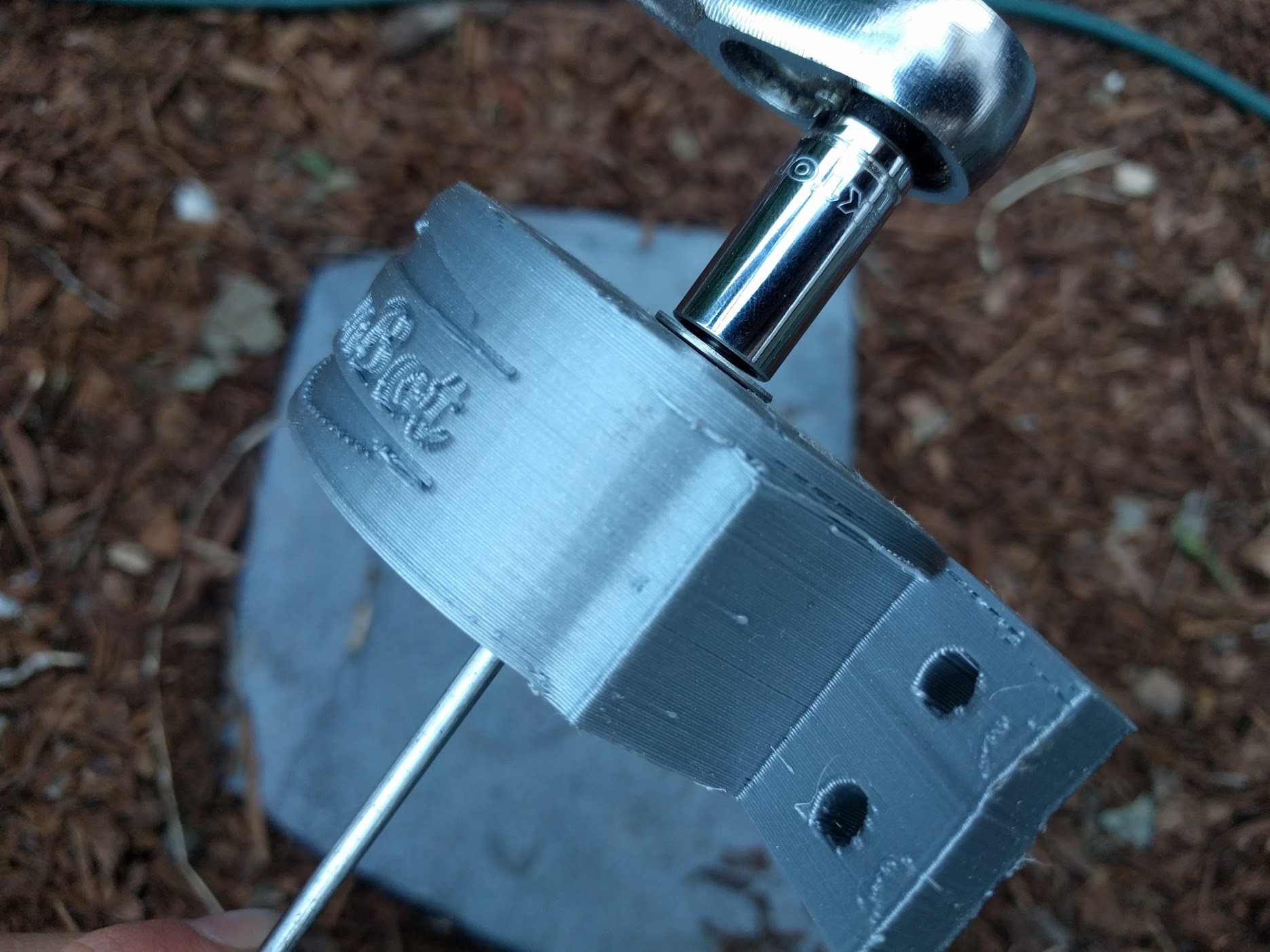
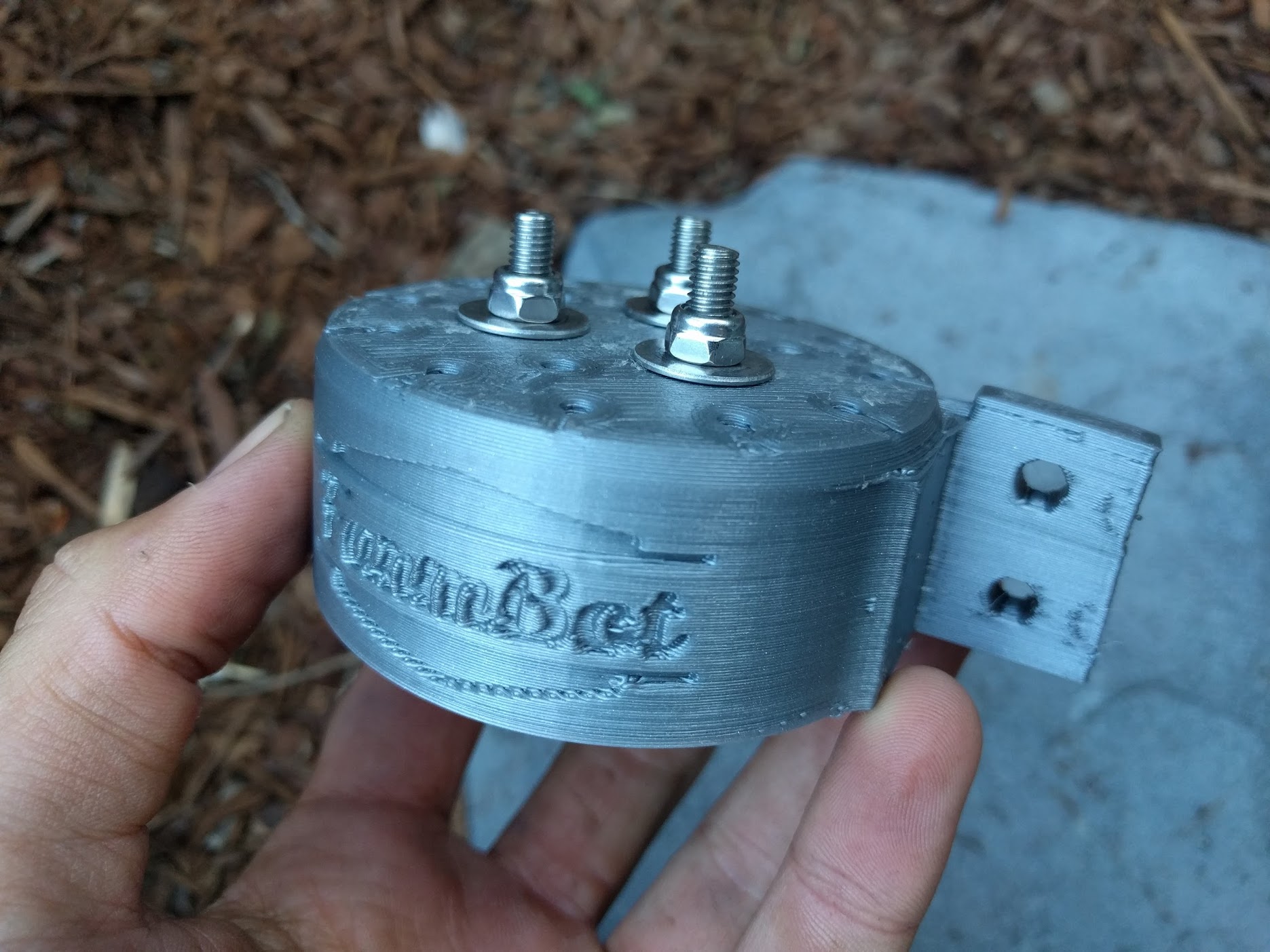
Repeat the process above for the two remaining UTM magnets.
Before tightening the last two locknuts...
Ensure that the polar orientation of all the UTM magnets are the same. You can do this by holding a fourth magnet near the UTM magnets. Without flipping the magnet in your hand, it should either be attracted to all of the UTM magnets, or repelled from all of the UTM magnets. Again, it doesn’t matter which way they are installed, as long as they are all the same with respect to each other.
Step 3: Install the Barbs
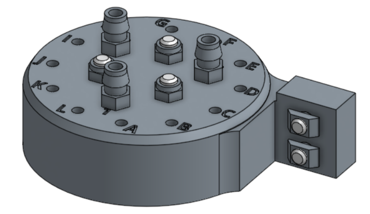
Use the 8mm wrench to screw in the three barbs to the UTM. The barbs should be inserted in the holes labelled 1, 2, and 3.
Step 4: Install the o-rings
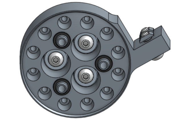
Slide three o-rings onto the UTM 1, 2, and 3 port cones. Each o-ring should be “seated” in the recess at the base of the port cone.
Step 5: Install the electronic contact screws
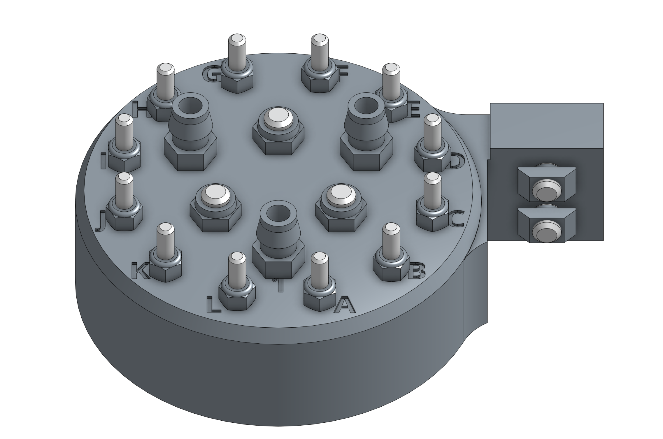
Place a spring on an M3 x 40mm screw, and then insert the screw into a lettered hole in the UTM.
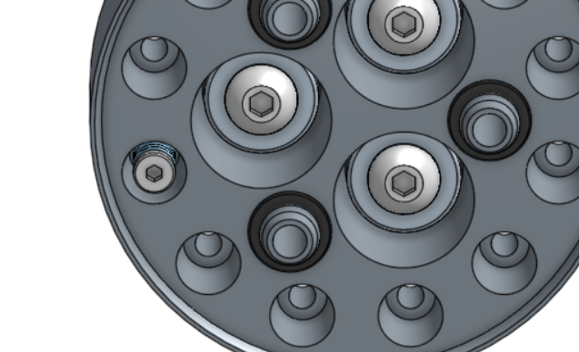
Using the 2mm hex driver and the 6mm wrench, attach an M3 locknut onto the screw. Tighten the locknut until the spring is slightly compressed.
Repeat for all holes A through L.
Step 6: Prepare the UTM Cover
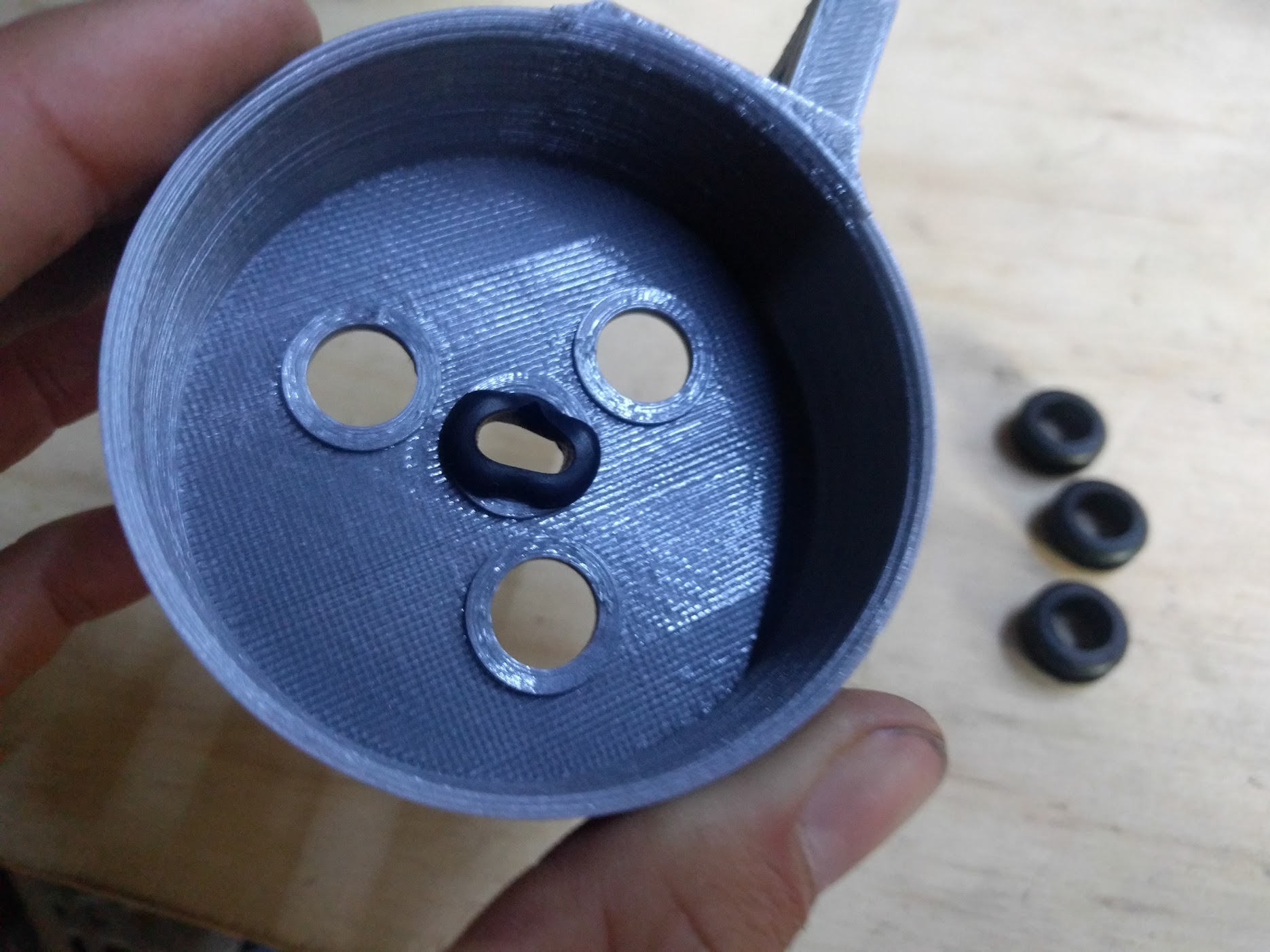
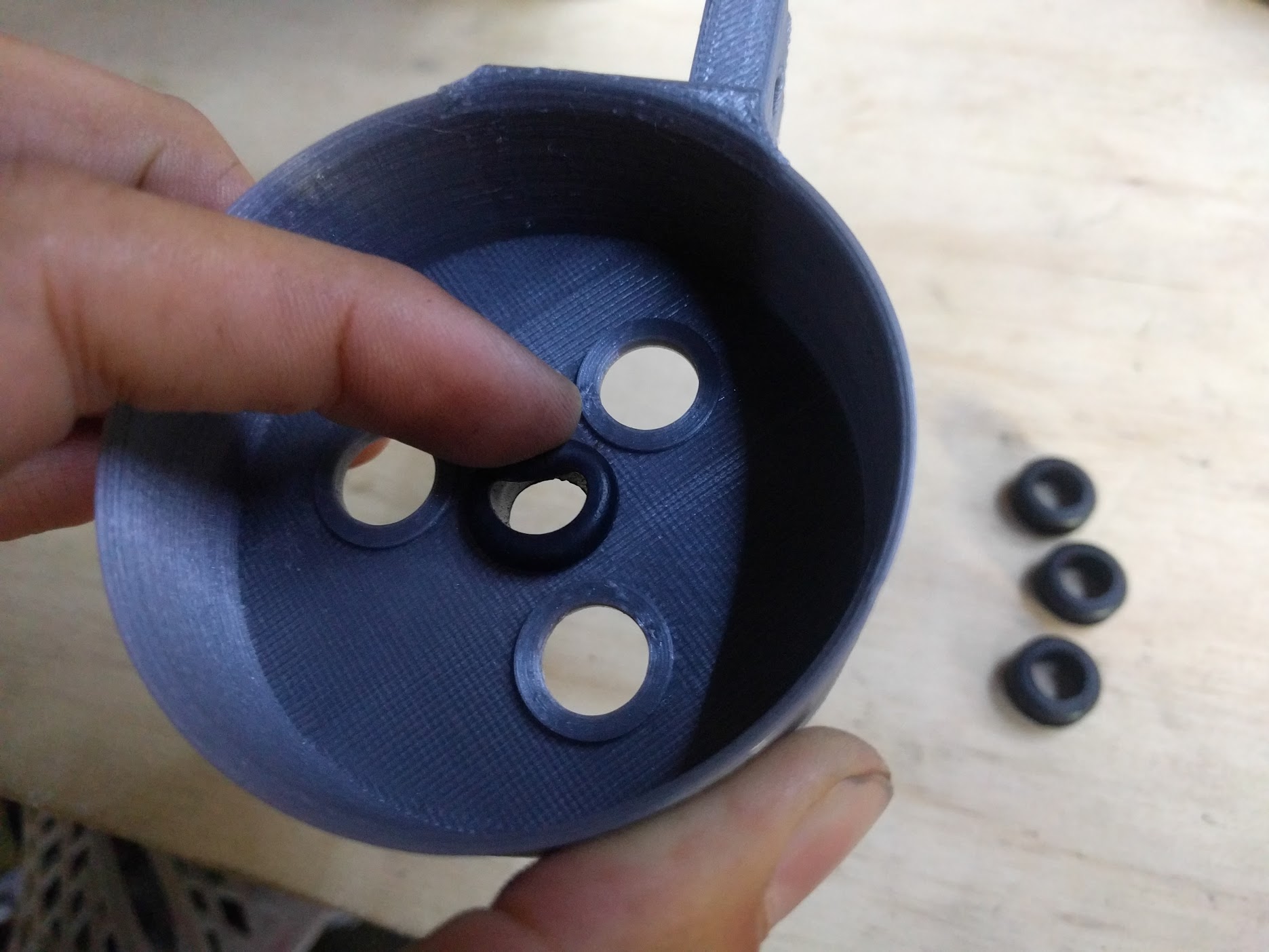
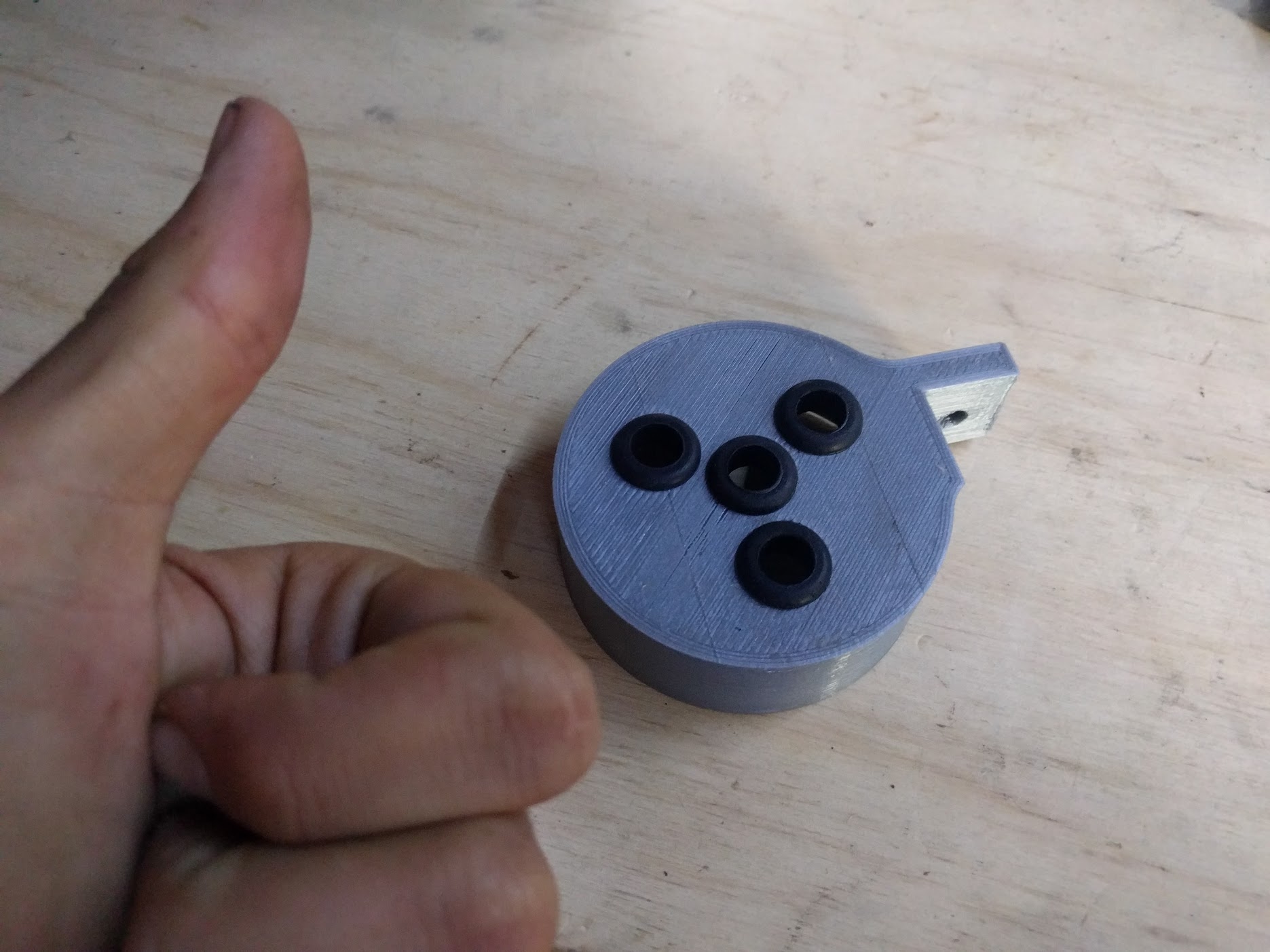
Insert four rubber seals into the UTM cover.
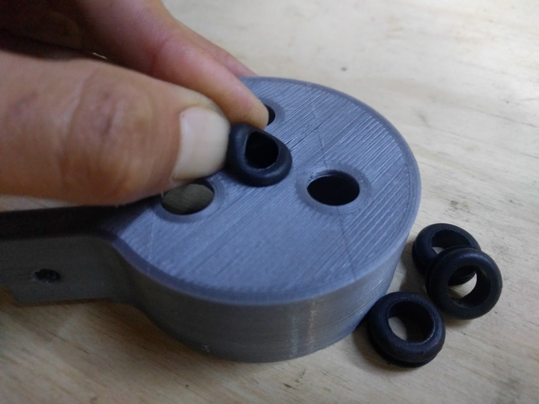
Ensure that the seal flanges are not folded or caught under themselves.
