Wire up the UTM
Step 1: Feed the Tubes and Cable
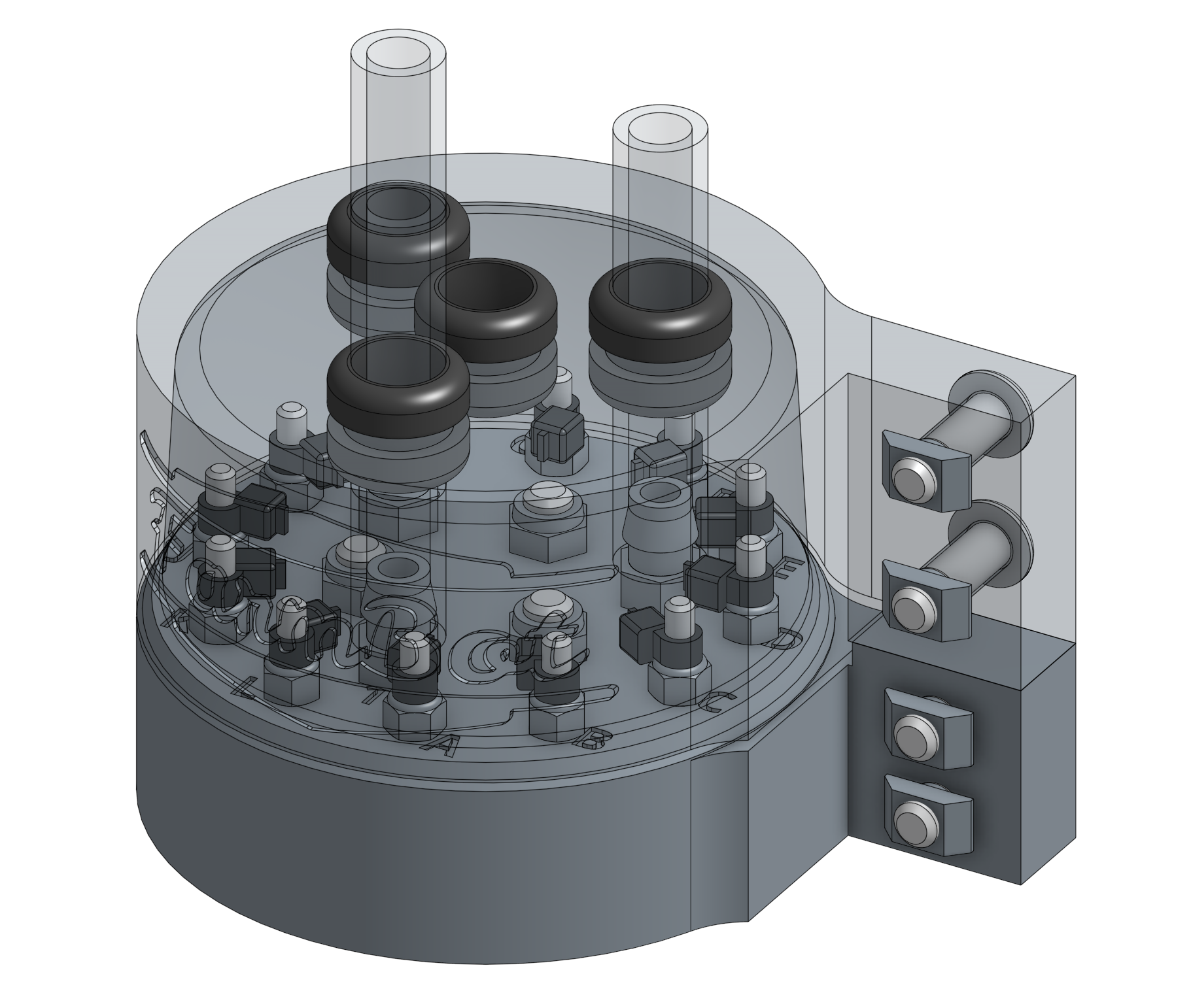
Push the UTM cable through the center hole in the UTM cover so that there is about 10cm of cabling beneath the cover. It may be difficult to do this because of the friction and tight seal created between the rubber seal and the cable. Be gentle and take your time. Some soapy water can facilitate the cable to slide through more easily, and will dry up within a day.
Push the vacuum tube through port 1 on the UTM cover so that there is about 10cm of tubing beneath the cover.
Push the extra peripheral tube through port 2 on the UTM cover so that there is about 10cm of tubing beneath the cover.
Push the water tube through port 3 on the UTM cover so that there is about 10cm of tubing beneath the cover.
Step 2: Wire up the UTM
Use the exacto blade to remove 5cm of the UTM cable outer rubber insulation.
Take your time
When removing the outer insulation, it is easy to accidentally cut through some of the smaller wires inside the cable, or cut through their insulation. Take your time to avoid accidentally doing this.
If you do accidentally sever one of the smaller wires, you must cut the entire cable down to an uncut section and start over.
Each small wire of the UTM cable is numbered with small white text. Fan out the wires and arrange them in order from 1 to 12.
Use the wire strippers to remove 0.5 to 1cm of insulation from each small wire.
Use a zip-tie to secure each wire to an M3 screw on top of the UTM according to the pin mapping table below.
Pin Mapping
Room for expansion
Only four of the 12 wires/UTM pins are currently mapped. This is because the currently available FarmBot tools only need these four pins to function, which means that the other eight pins are ready for you to map however you desire. Dreaming of a USB, I2C, or PWM based tool? Go right ahead and expand upon your FarmBot’s abilities with custom tools of your own!
| UTM Pin/UTM Wire | is connected to | and used for |
|---|---|---|
| A/1 | Ground (0V) on Arduino/RAMPS | Ground |
| B/2 | +5V on Arduino/RAMPS | Tool verification |
| C/3 | Pin D16 on Arduino/RAMPS - Digital-In | Tool verification |
| D/4 | Pin A13 on Arduino/RAMPS - Analog-In | Soil sensor and other analog signal tools |
| E/5 | Your choice | Anything you want |
| F/6 | Your choice | Anything you want |
| G/7 | Your choice | Anything you want |
| H/8 | Your choice | Anything you want |
| I/9 | Your choice | Anything you want |
| J/10 | Your choice | Anything you want |
| K/11 | Your choice | Anything you want |
| L/12 | Your choice | Anything you want |
Step 3: Install the UTM and Cover onto the Z-Axis
Slide the vacuum tube onto the port 1 barb, the extra tube onto the port 2 barb, and the water tube onto the port 3 barb.
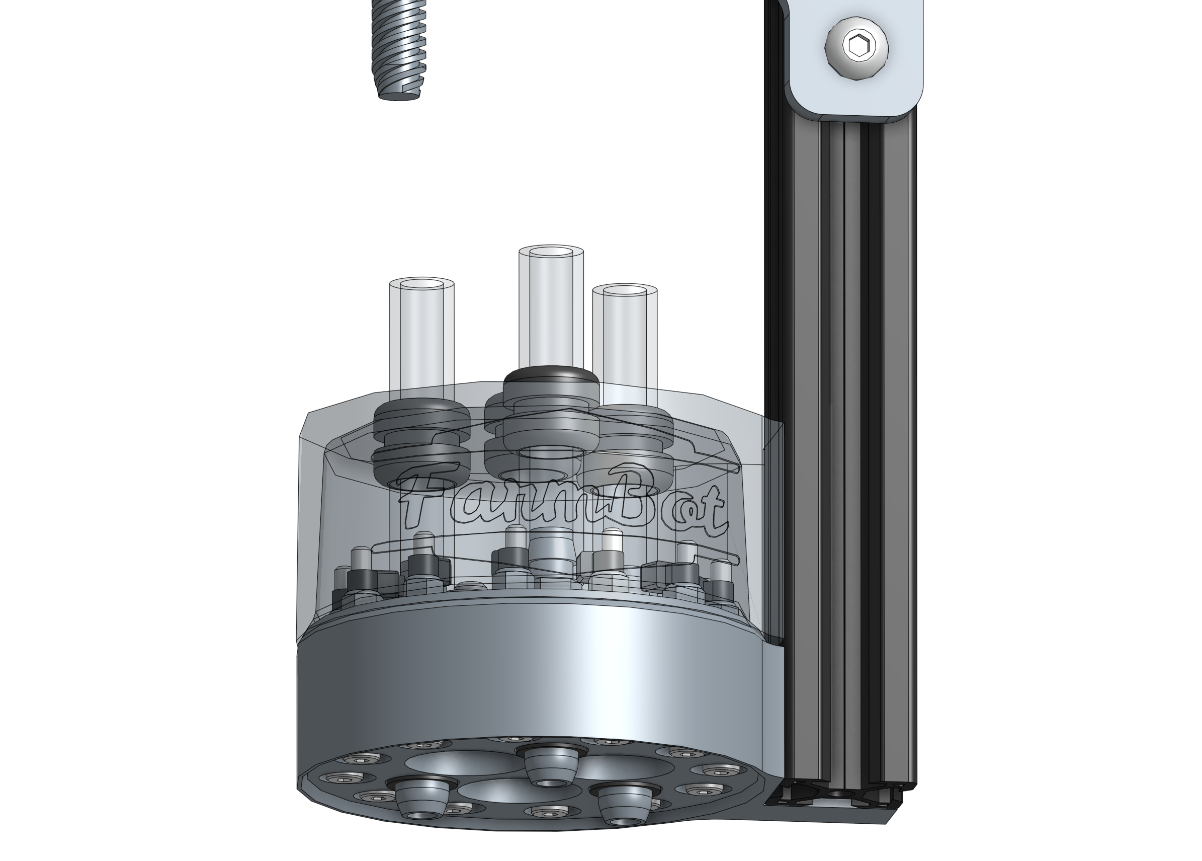
Slide the UTM cover down the tubes and cable until it sits flush against the top of the UTM.
Keep it sealed
The UTM cable’s outer insulation must maintain contact with the UTM cover’s rubber seal in order to keep rain out. It is best to keep 1cm or more of the cable’s insulation inside of the cover.
Insert two M5 x 10mm screws through the UTM cover mounting holes and then lightly thread an M5 tee nut onto each. Repeat for the UTM.

Slide the UTM cover and UTM onto the z-axis extrusion. The plastic brackets should be positioned on the backside of the extrusion. The bottom of the UTM should be flush with the bottom of the extrusion, and the bottom of the UTM cover should be flush with the top of the UTM.
Tighten all four M5 screws with the 3mm hex driver.

Woo hoo!
You just finished the most tedious and arguably difficult part of building your FarmBot. Take a deep breath, do a stretch, and grab a snack - you deserve it!