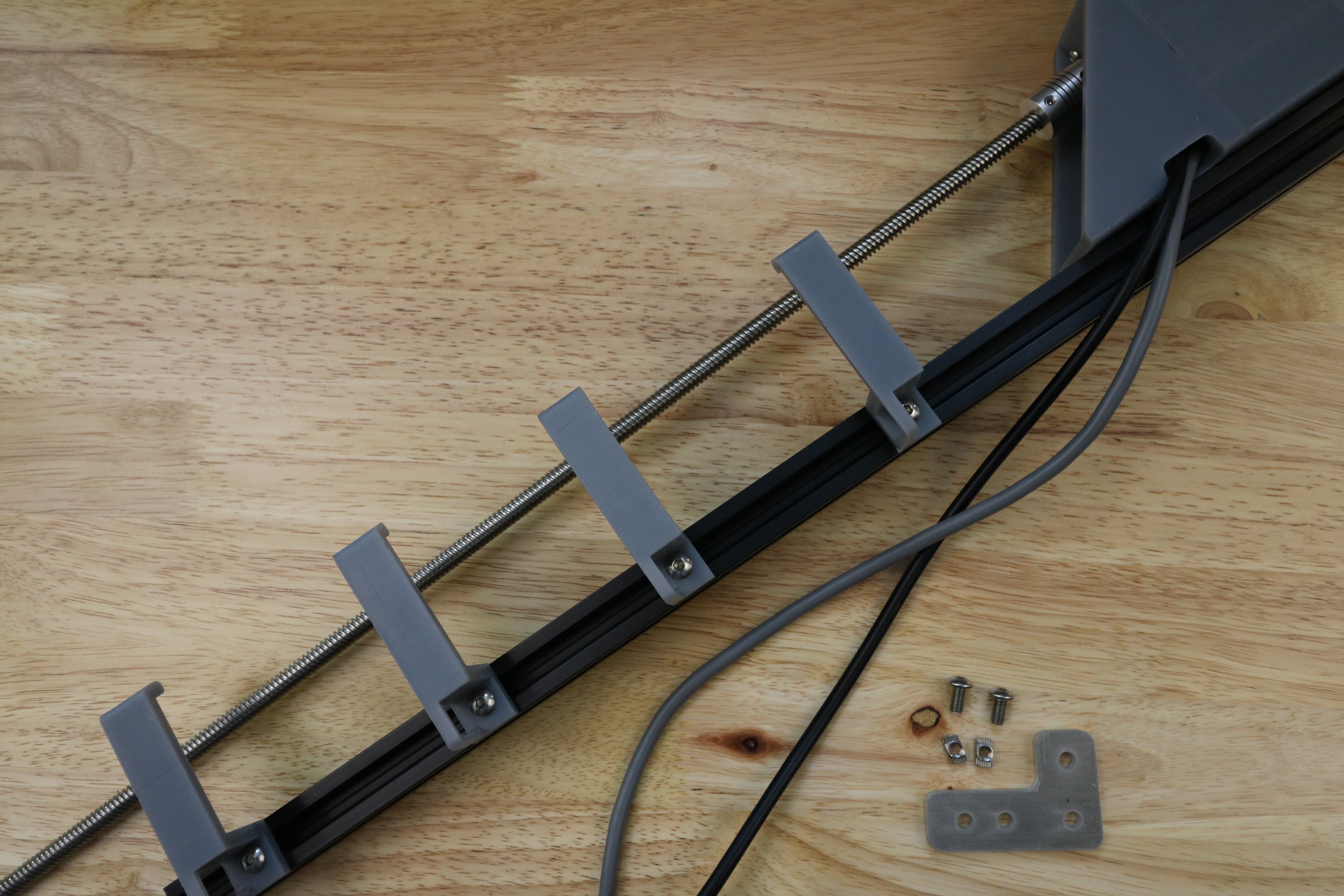
Assemble the Z-Axis
30 minutes
This is the estimated time it will take to assemble the z-axis.
Step 1: Gather the Parts and Tools
Gather all the parts from the table below and lay them out in a logical manner. To complete the assembly, you will also need the following tools:
- 2mm hex (allen) wrench
- 3mm hex (allen) wrench
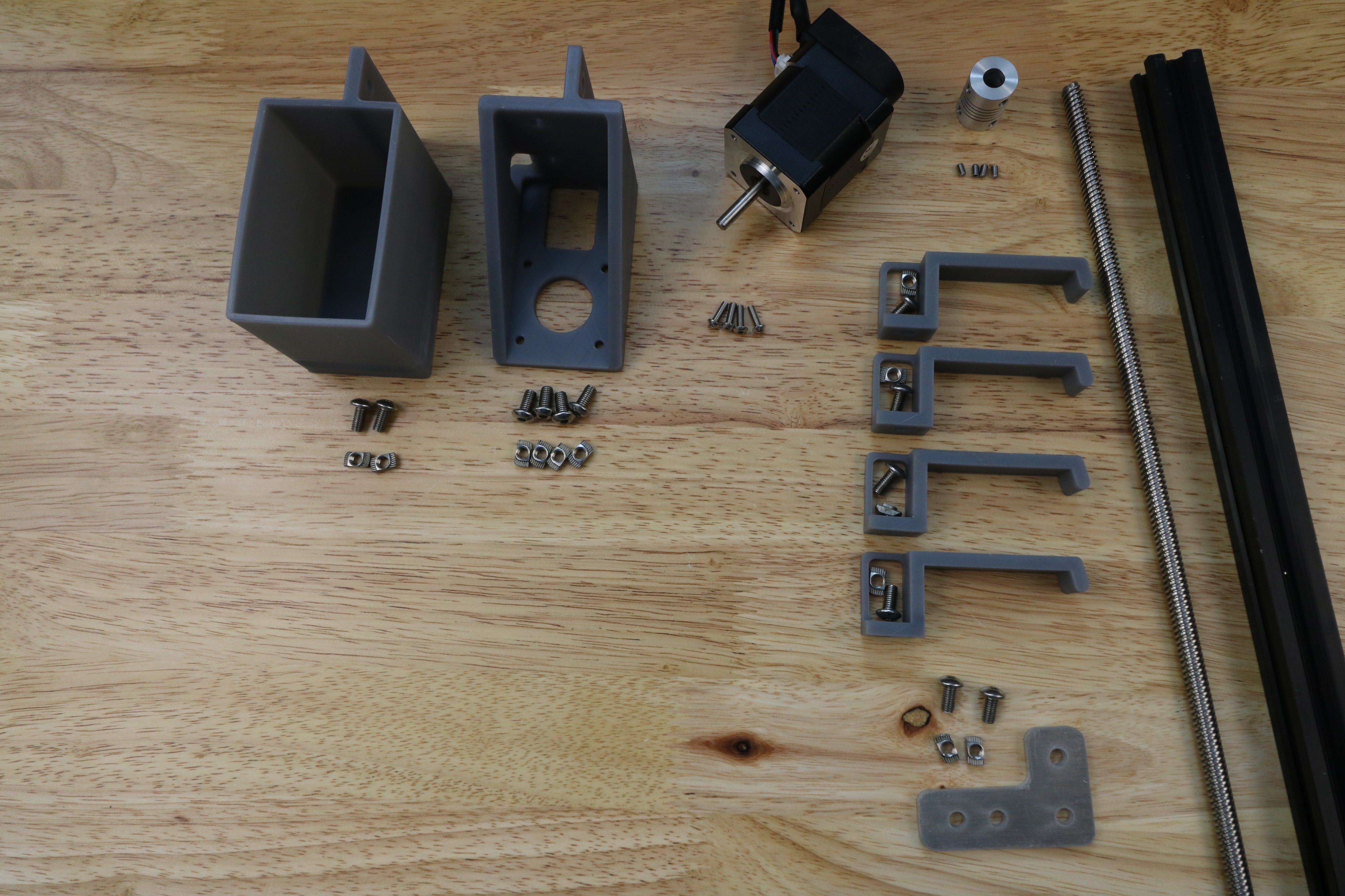
| Qty. | Component |
|---|---|
| 1 | Z-Axis Extrusion (20 x 20 x 1000mm) |
| 4 | M3 x 10mm Screws |
| 10 | M5 x 10mm Screws |
| 2 | M5 x 16mm Screws |
| 2 | M5 x 25mm Screws |
| 2 | M5 x 20mm Spacers |
| 2 | M5 Washers |
| 2 | M5 Locknuts |
| 12 | M5 Tee Nuts |
| 1 | Z-Axis Motor Bracket |
| 1 | Vertical Motor Housing |
| 4 | Z-Axis Cable Carrier Guides |
| 1 | NEMA 17 Stepper Motor and Rotary Encoder with 3500mm length cables |
| 1 | 5mm to 8mm Flex Coupling |
| 1 | 8 x 1000mm Leadscrew |
Step 2: Attach the Stepper Motor to the Z-Axis motor bracket
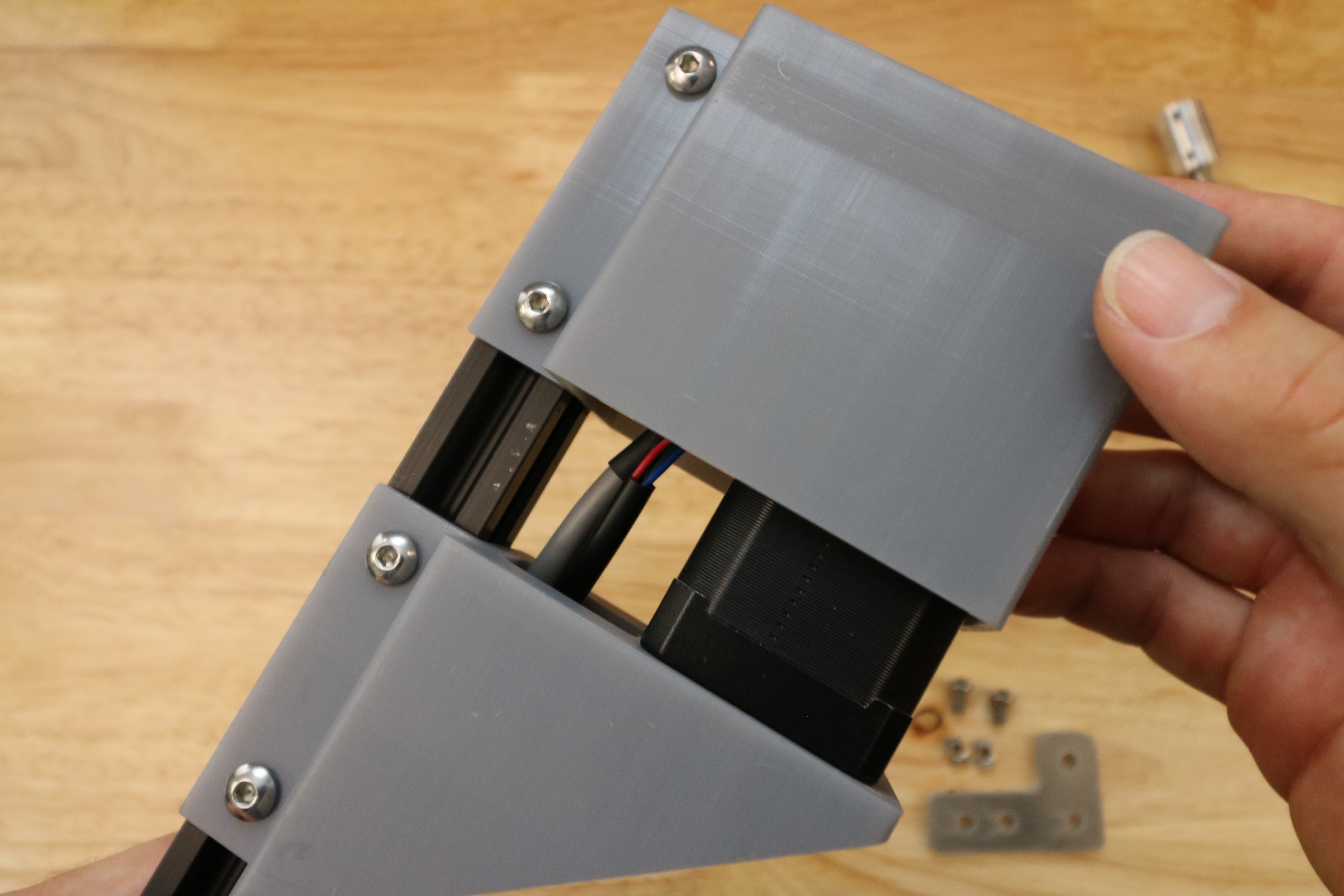
Feed the z-axis motor/encoder cables through the z-axis motor mount.
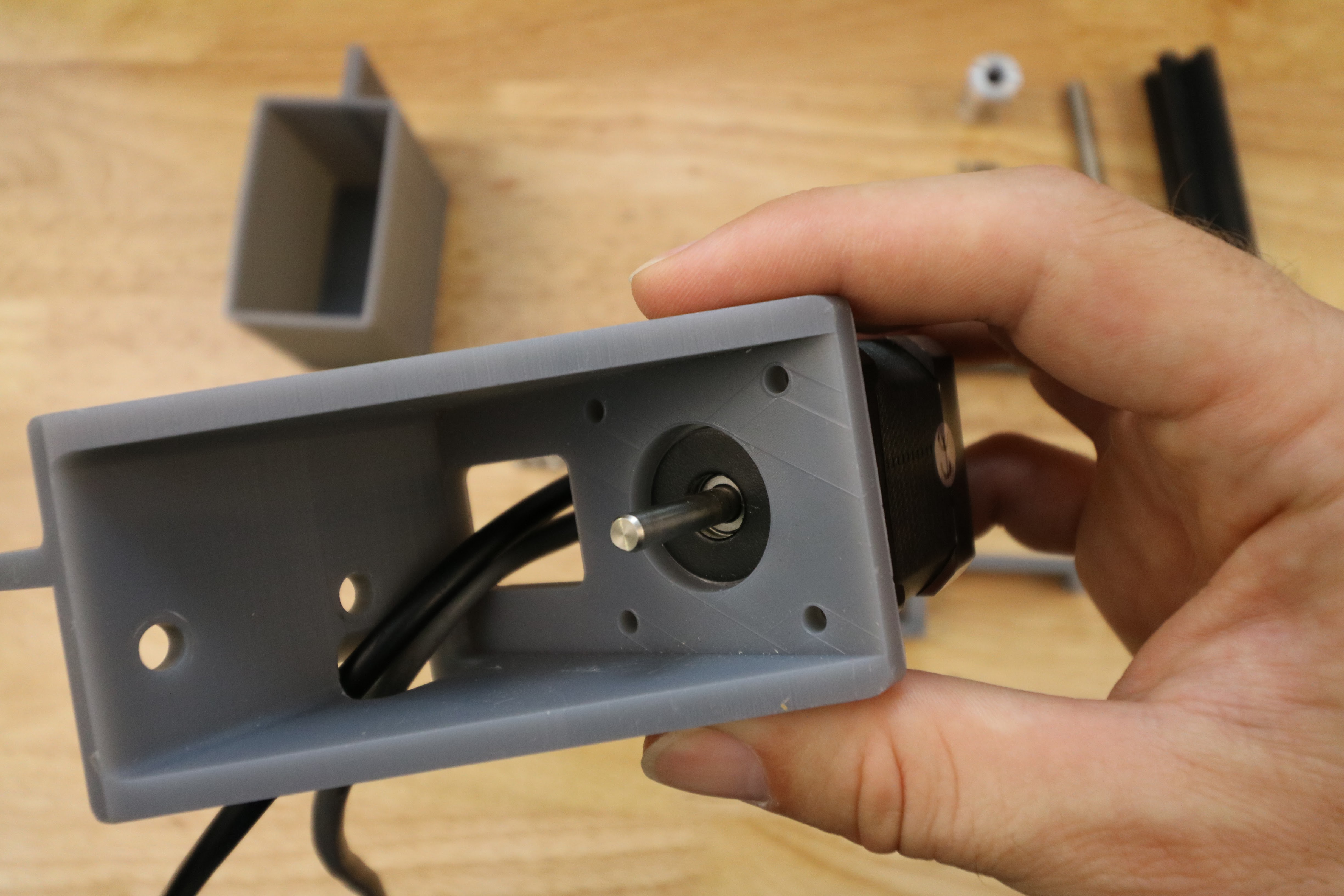
Attach the z-axis stepper motor to the z-axis motor mount using four M3 x 10mm screws.
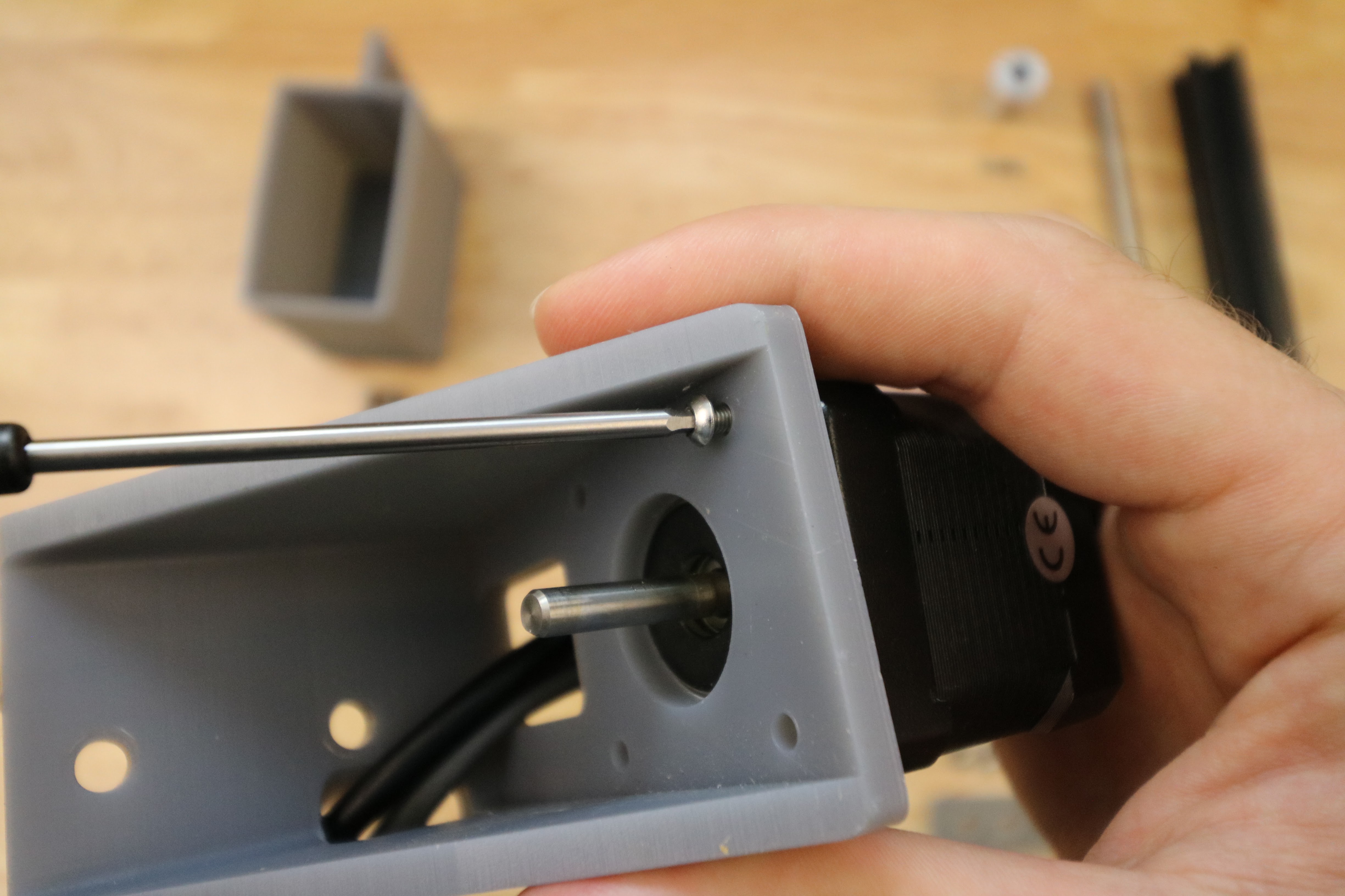
Step 3: Attach the motor to the z-axis extrusion
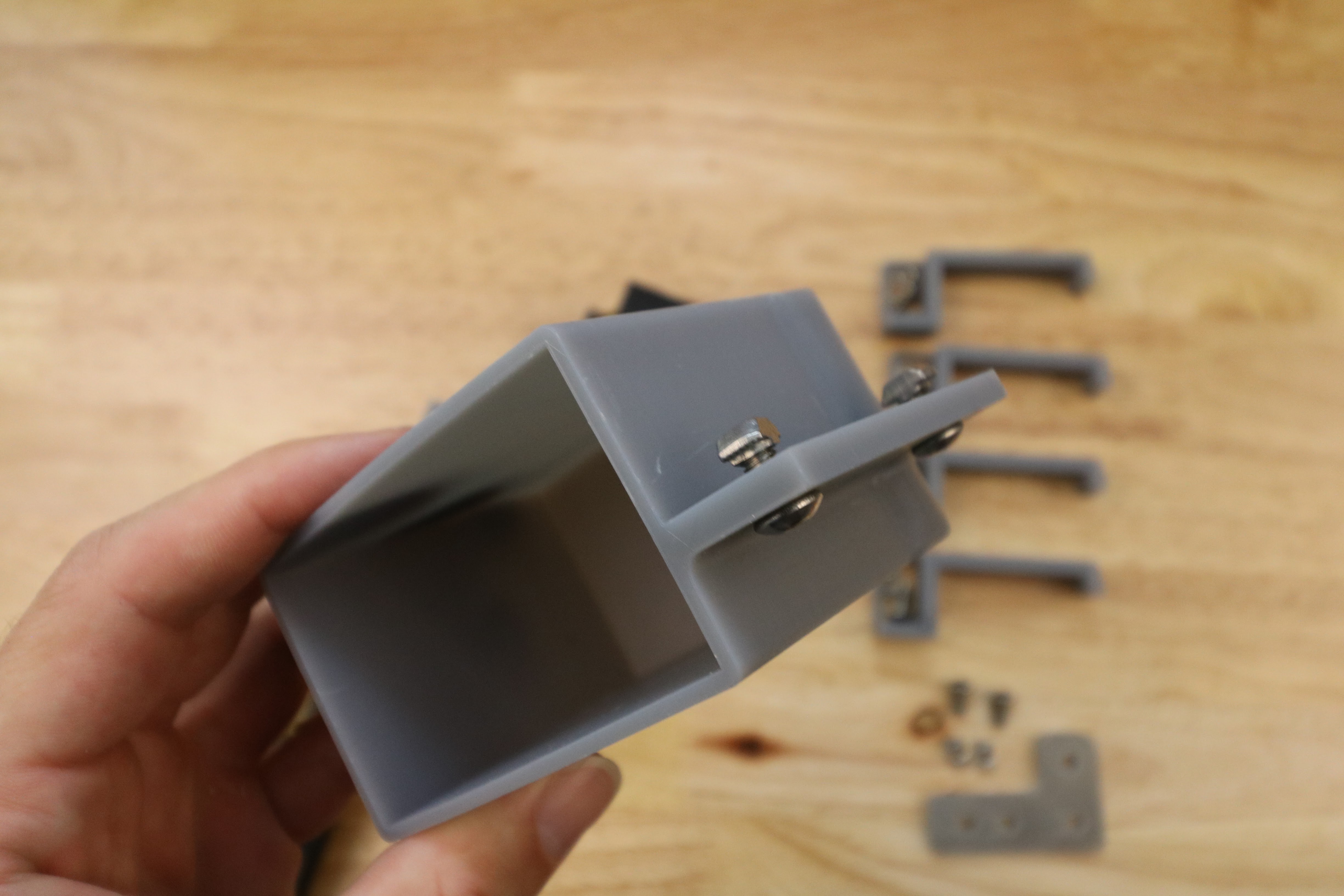
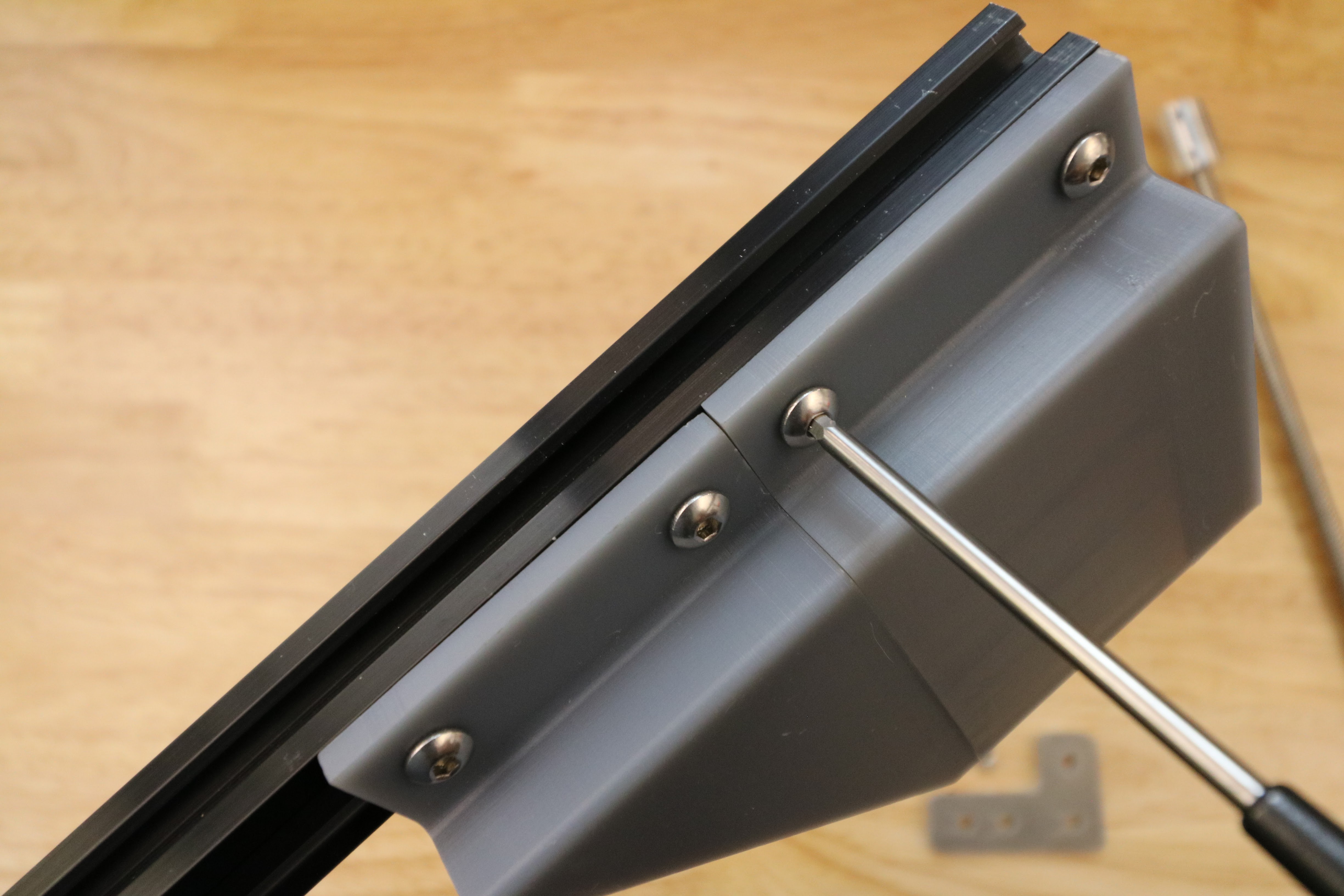
Partially screw two M5 x 10mm screws and M5 tee nuts into the z-axis motor bracket.
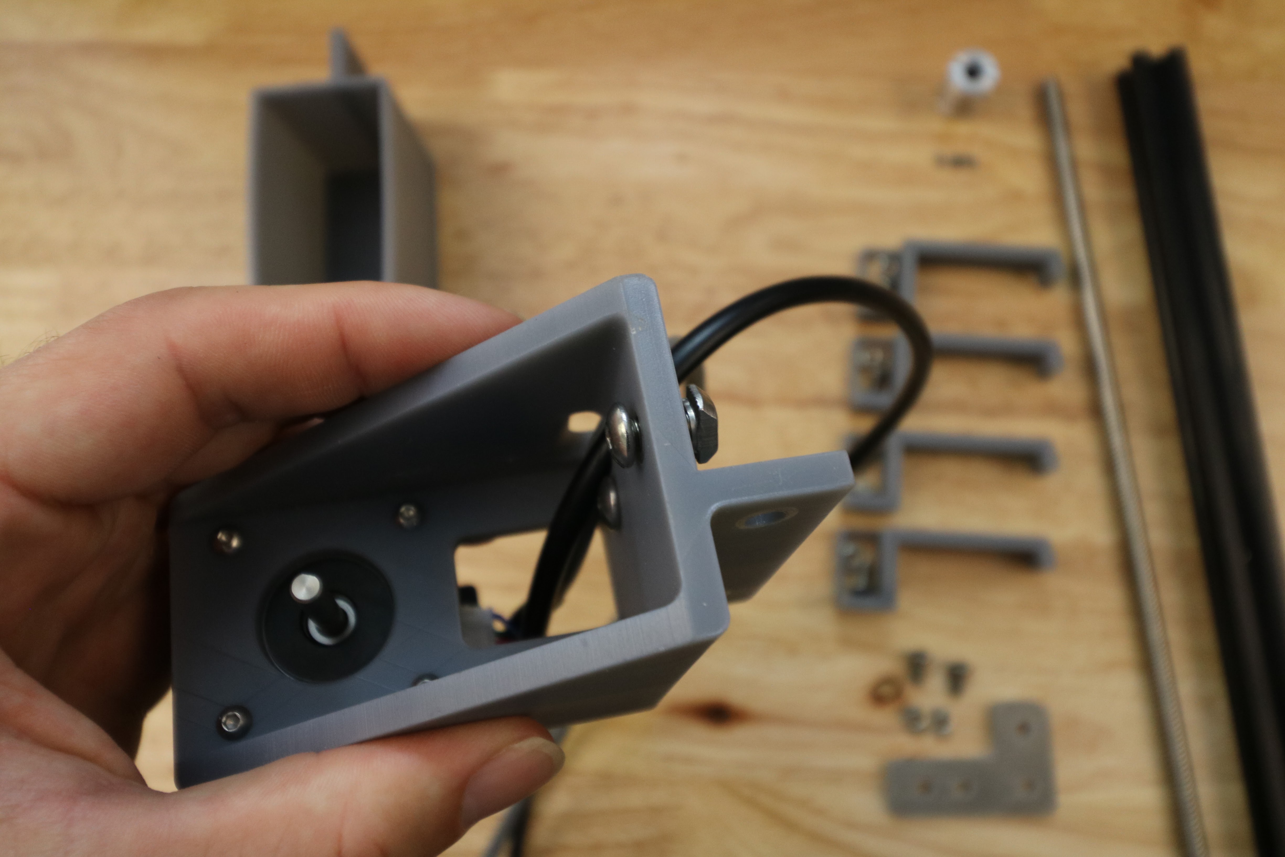

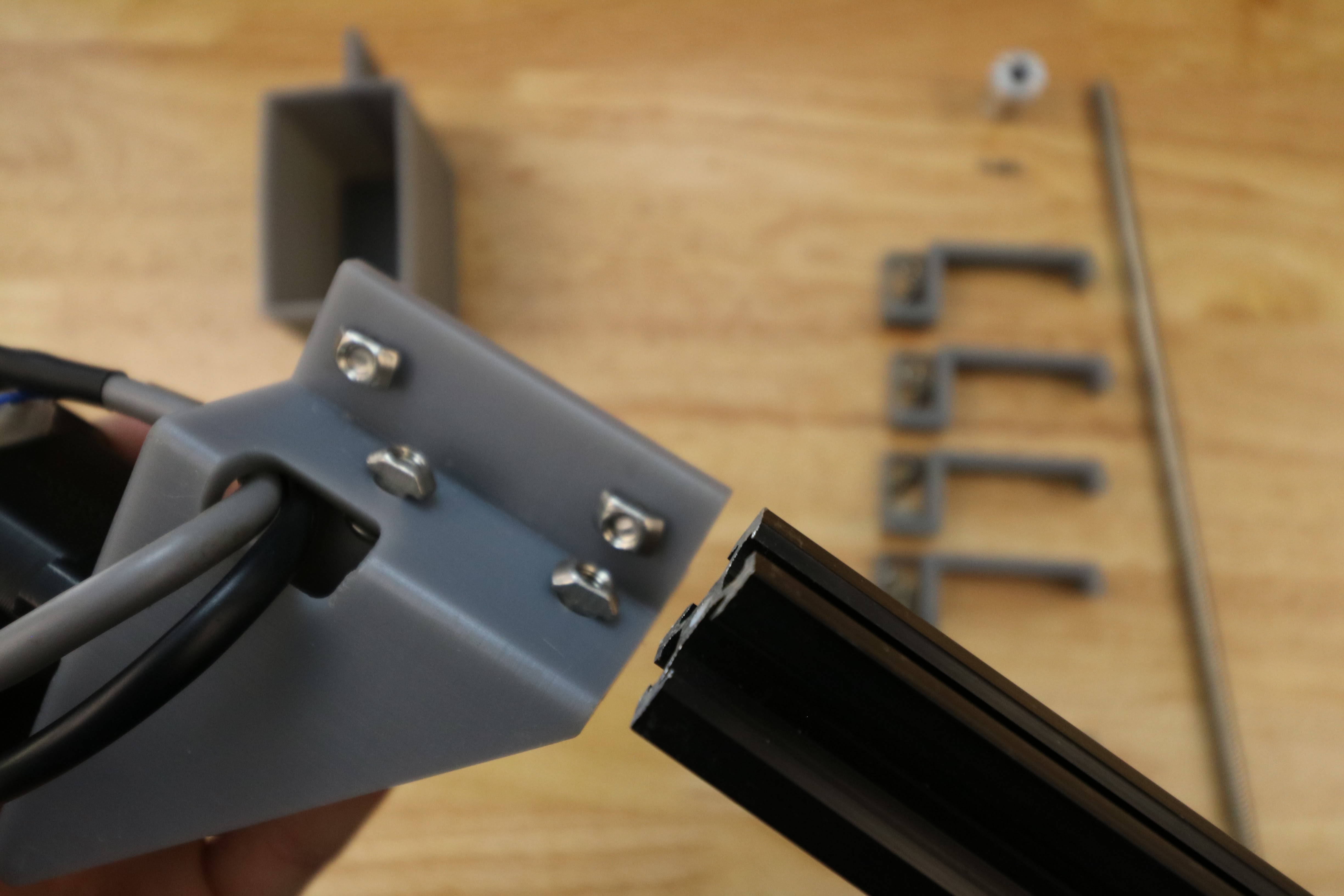
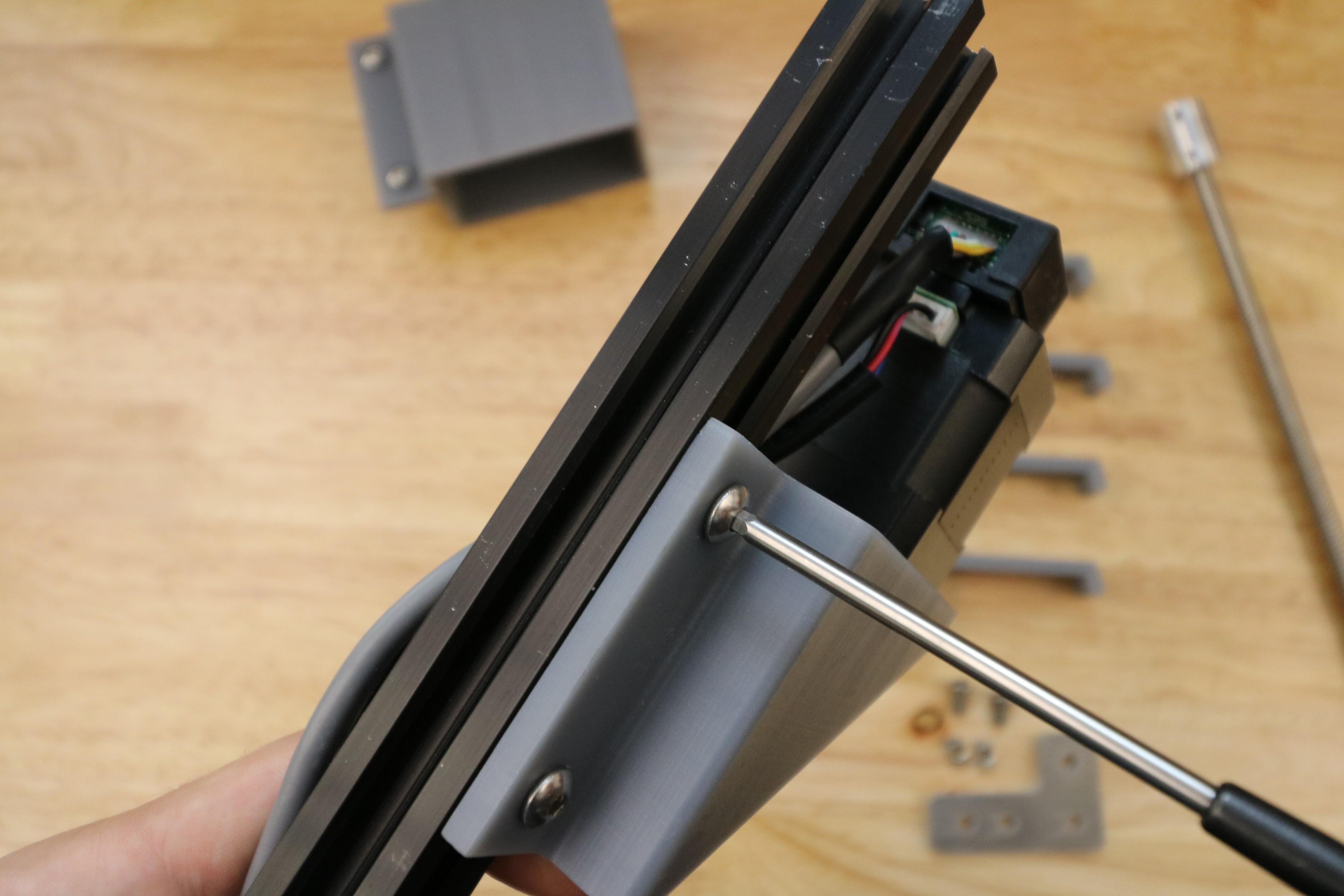
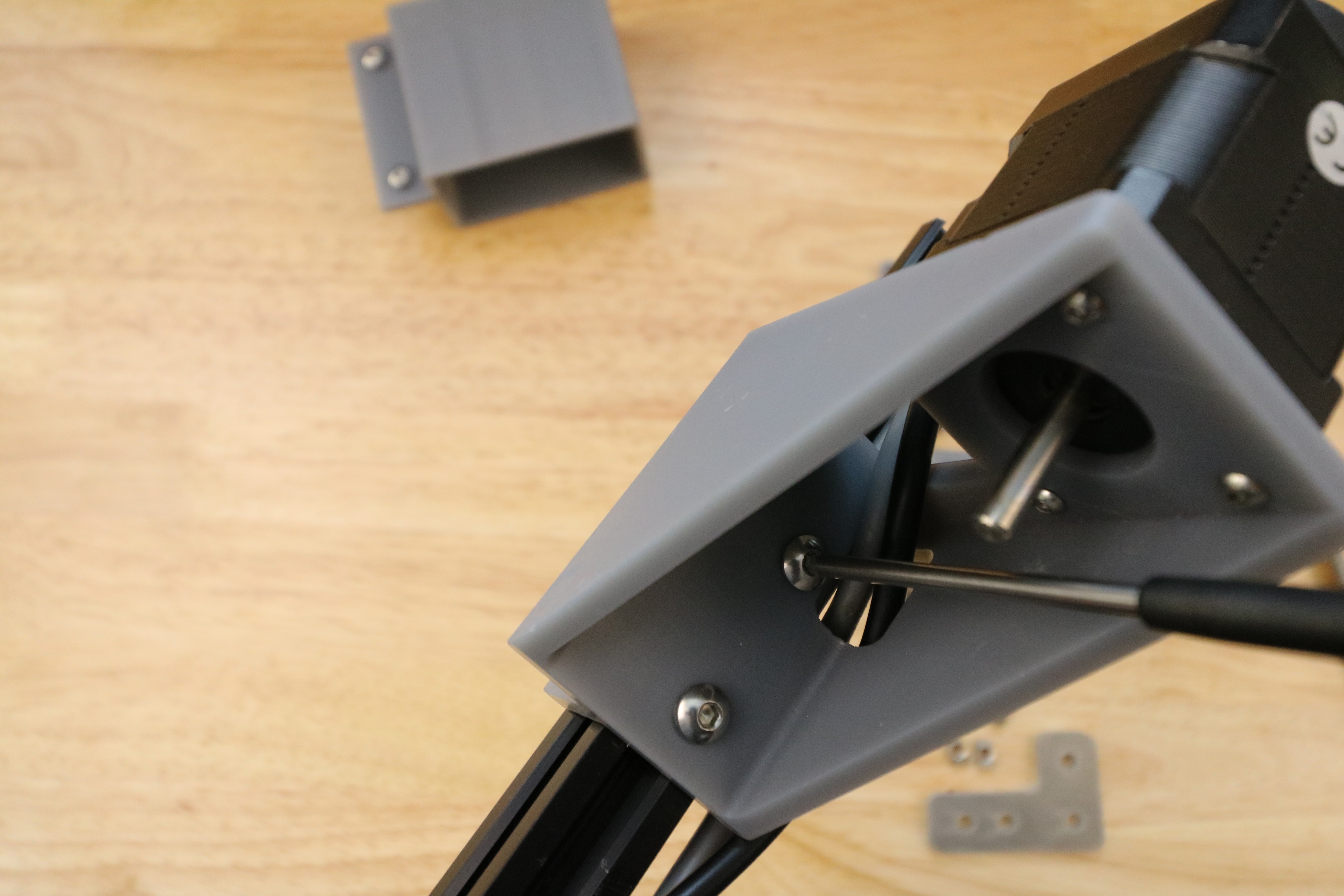
Tighten the z-axis motor mount onto the z-axis extrusion.

Step 4: Attach the Leadscrew
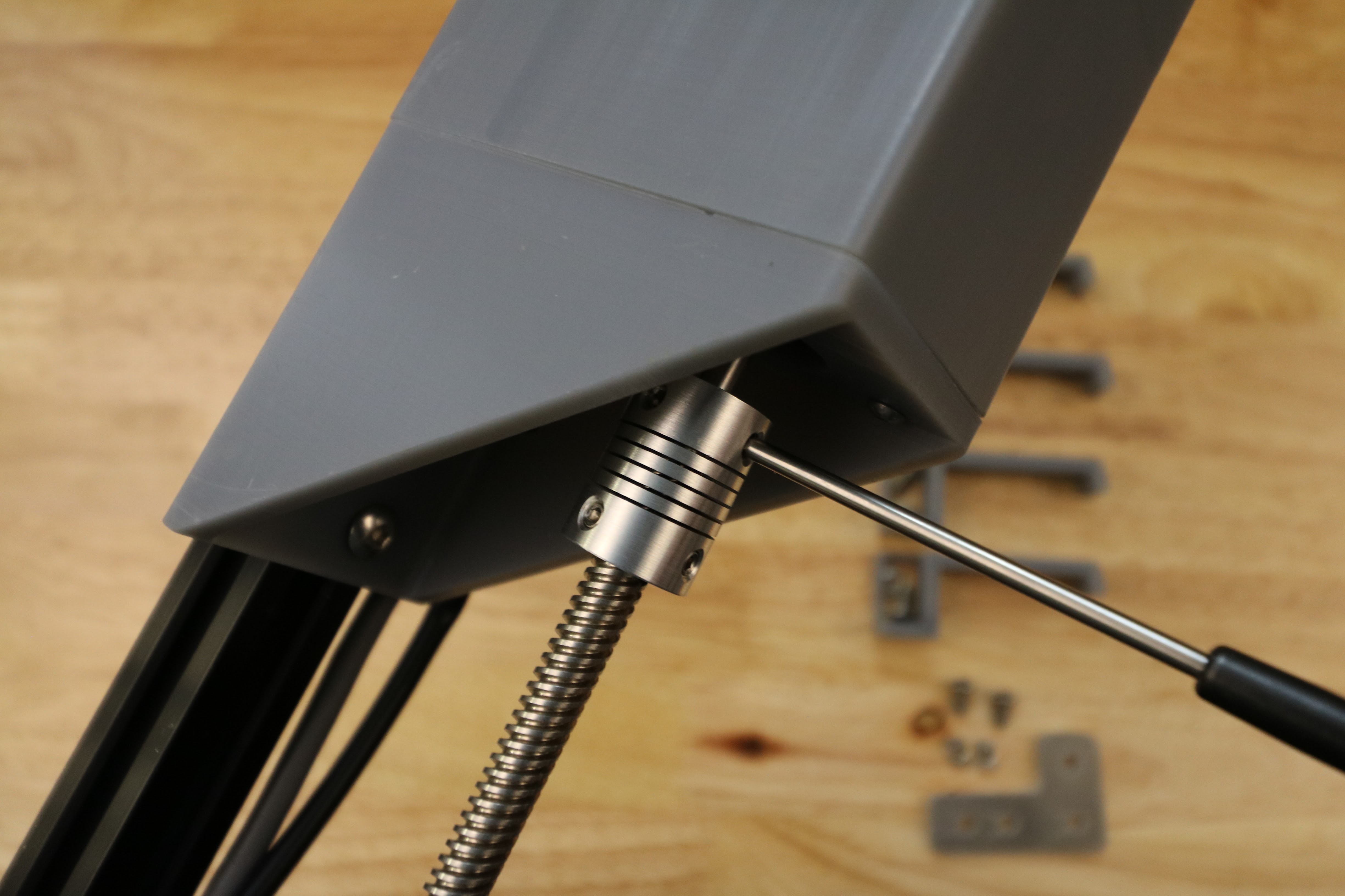
Tighten the 8mm side of the 5 to 8mm flex coupling onto the leadscrew.
Tighten the 5mm side of the 5 to 8mm flex coupling onto the shaft of the z-axis motor.
Step 5: Attach Z-Axis Cable Carrier Guides
Partially screw two M5 x 10mm screws and M5 tee nuts into the z-axis cable carrier guide.
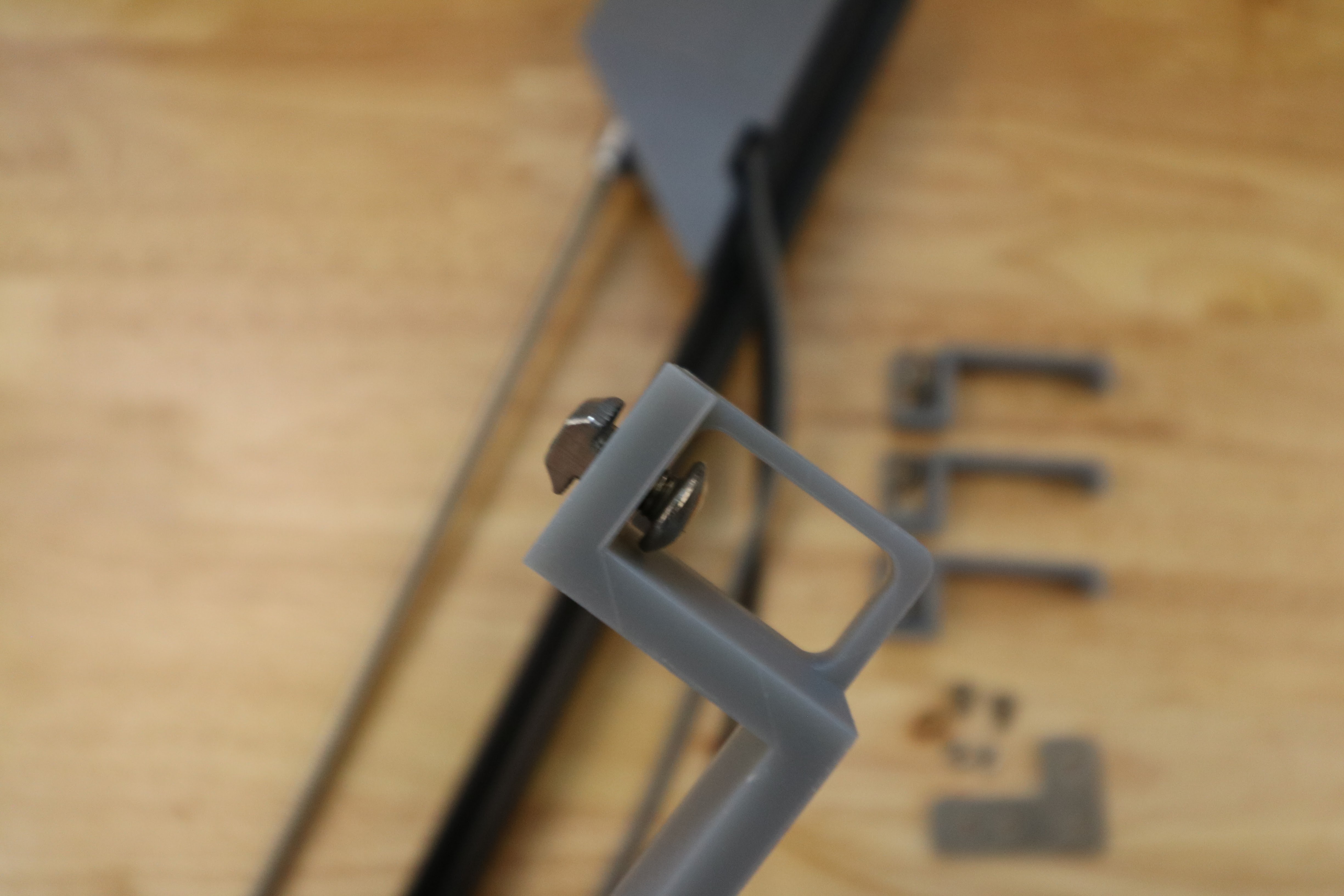
Insert into extrusion and tighten.
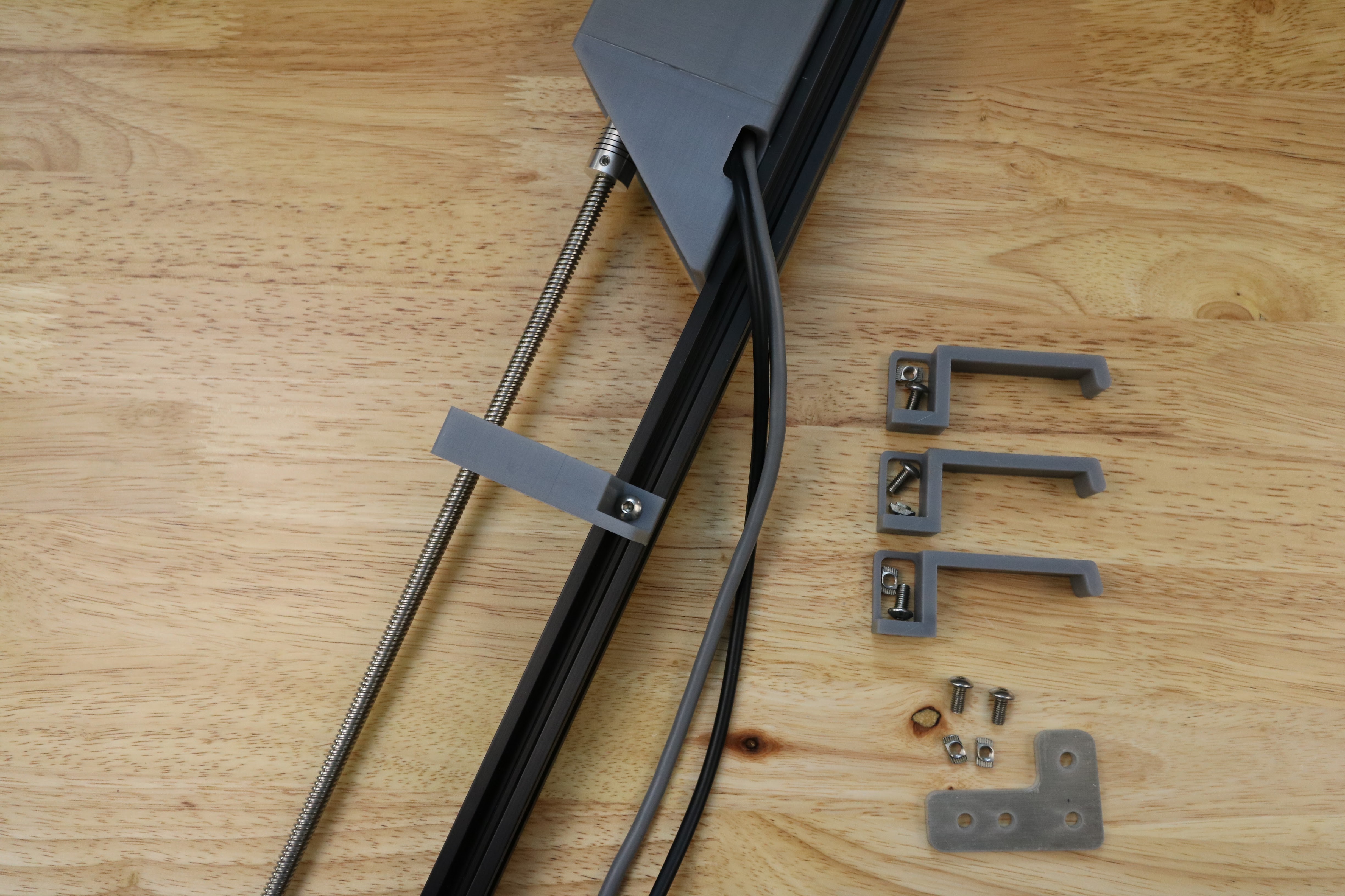
Repeat for other guides.
