Cross-Slide and Z-Axis
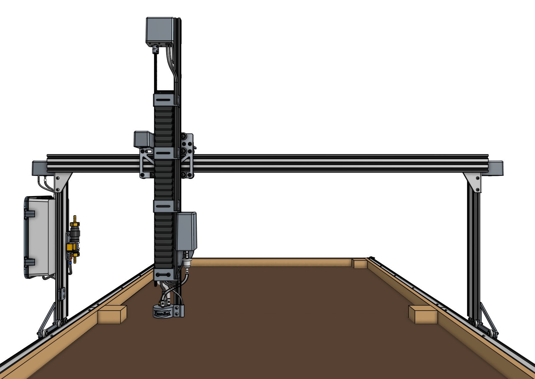
Documentation and assembly instructions for the FarmBot Genesis cross-slide and Z-axis
30 minutes
This is the estimated time it will take to assemble the cross-slide and Z-axis onto the gantry.
Step 1: Add the cable carrier mount
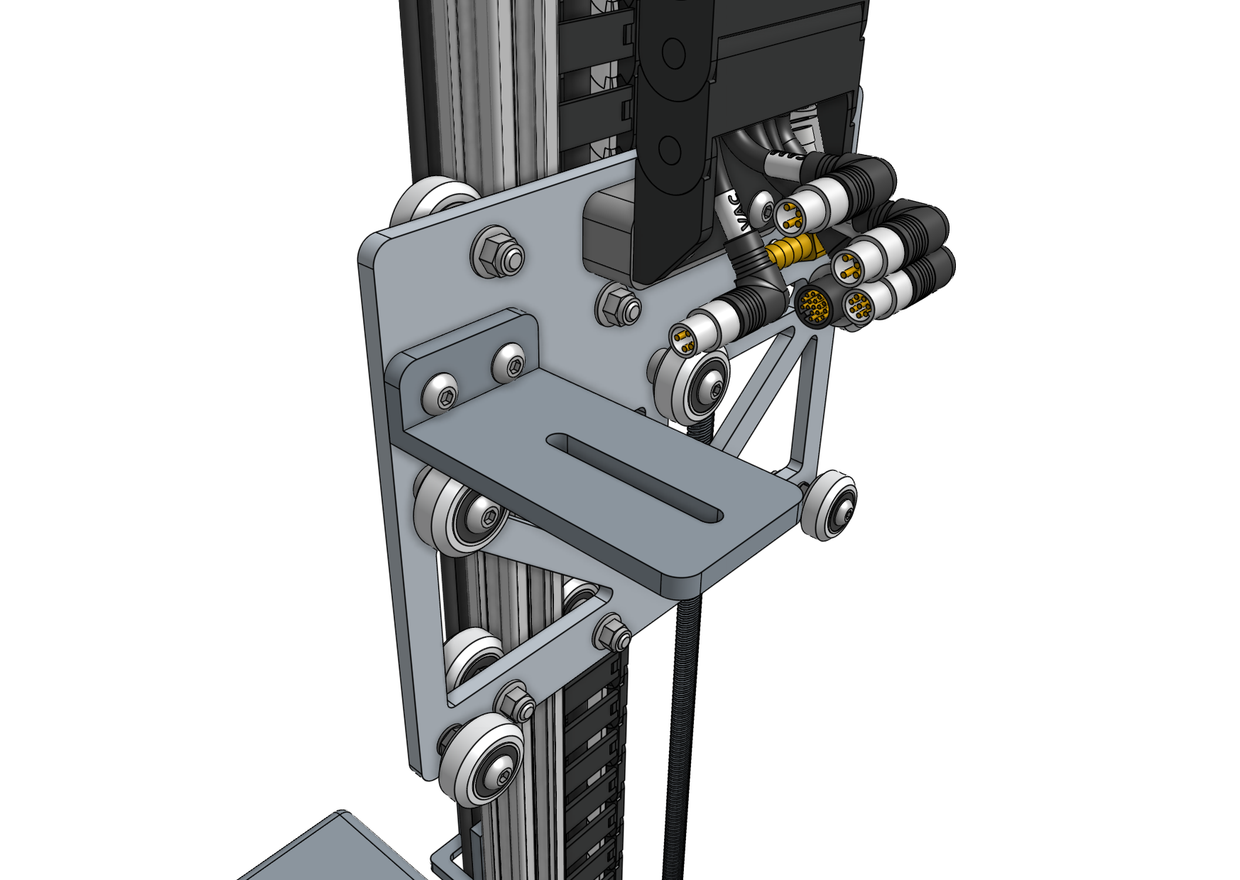
Attach the 80mm cable carrier mount to the cross-slide plate using two M5 x 16mm screws and M5 flange locknuts.
Step 2: Slide the cross-slide onto the gantry main beam
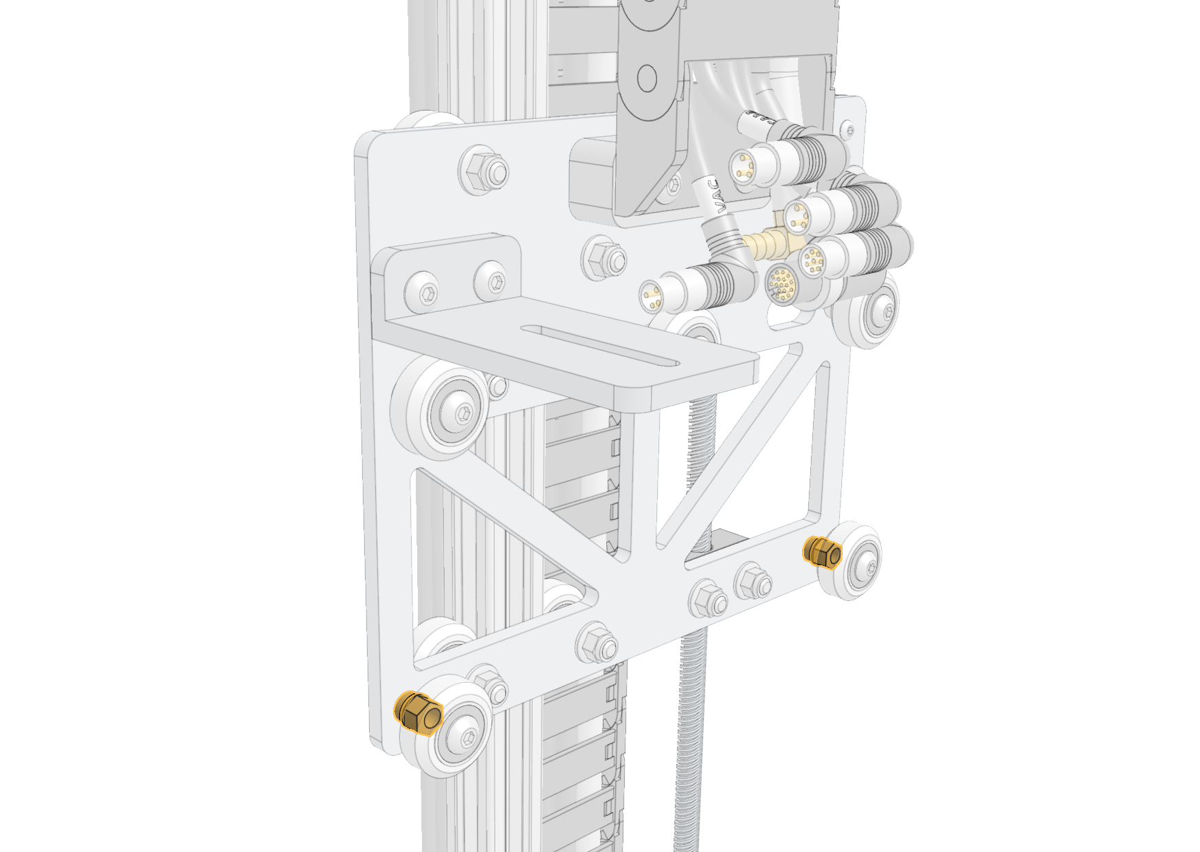
In order for the cross-slide to slide smoothly and wobble-free on the gantry main beam, you must adjust the eccentric spacers of the bottom two V-wheels. Adjust the eccentric spacers using the eccentric spacer adjustment reference guide.
Then slide the cross-slide onto the gantry main beam from the side opposite the electronics box.
You may need to manually rotate the leadscrew to raise the Z-axis so it clears the gantry wheel plate.
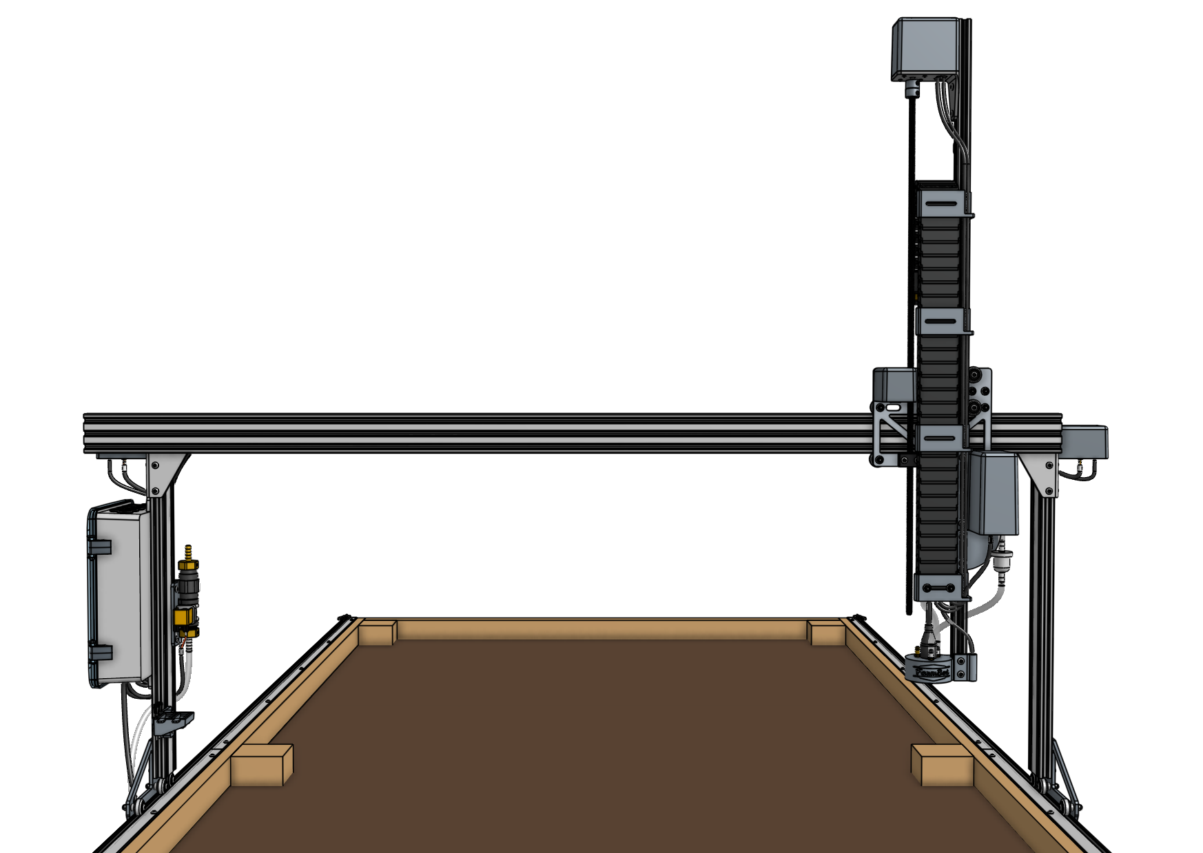
The cross-slide should move easily across the full width of the gantry. If you feel any significant resistance, re-adjust the eccentric spacers so that there is less resistance to movement.
On Genesis XL models, pay special attention to the joint between the two gantry main beams. If there is any significant bump or resistance to movement at the joint, use 150 grit sand paper to sand away the bump.
Step 3: Feed and secure the belt
Secure one end of the short belt to a belt clip using a belt sleeve and then attach the clip to the end of the gantry main beam using two M5 x 10mm screws and a 20mm nut bar. The tab of the belt clip should be oriented towards the front of the FarmBot. Refer to the belt installation guide for reference.
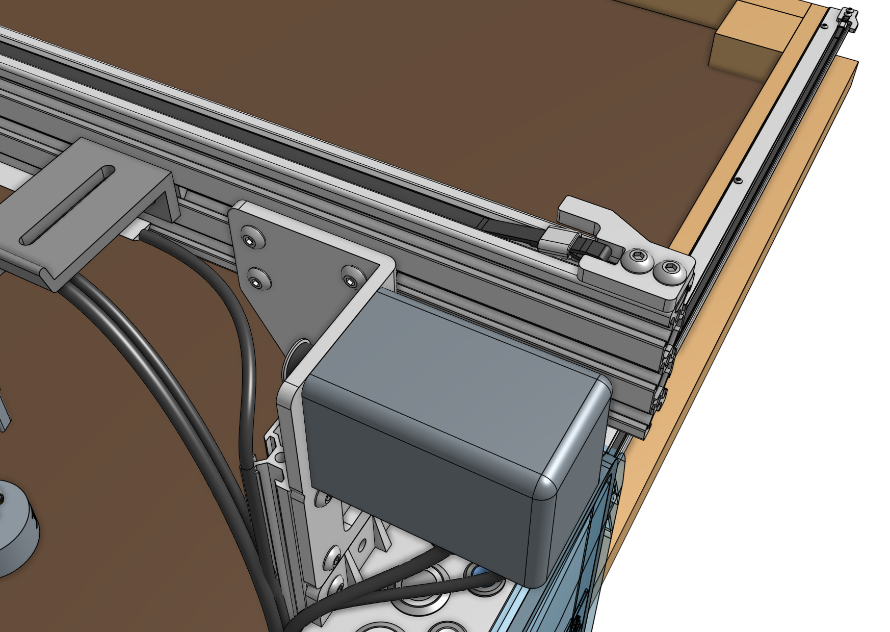
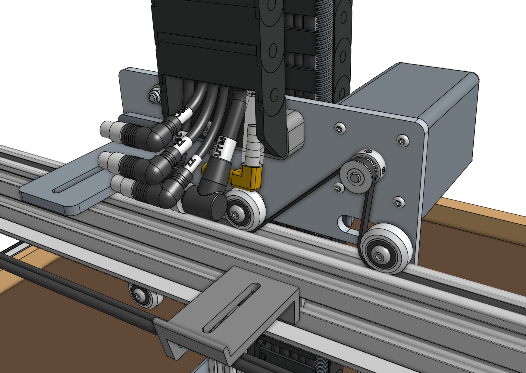
Feed the belt under the first V-wheel of the cross-slide, then over the pulley and under the remaining two V-wheels. The flat side of the belt should be in contact with the V-wheels while the toothed side should engage with the teeth on the pulley.
Make sure that the belt is not twisted anywhere.
Secure the belt at the other end of the gantry with another belt clip, 20mm nut bar, and two M5 x 10mm screws. Ensure there is a small amount of tension on the belt once everything is in place.
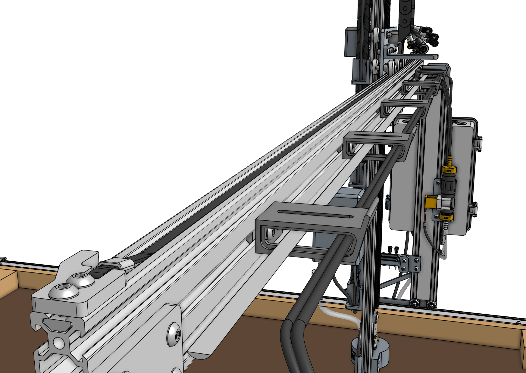
Step 4: Attach the cable carrier
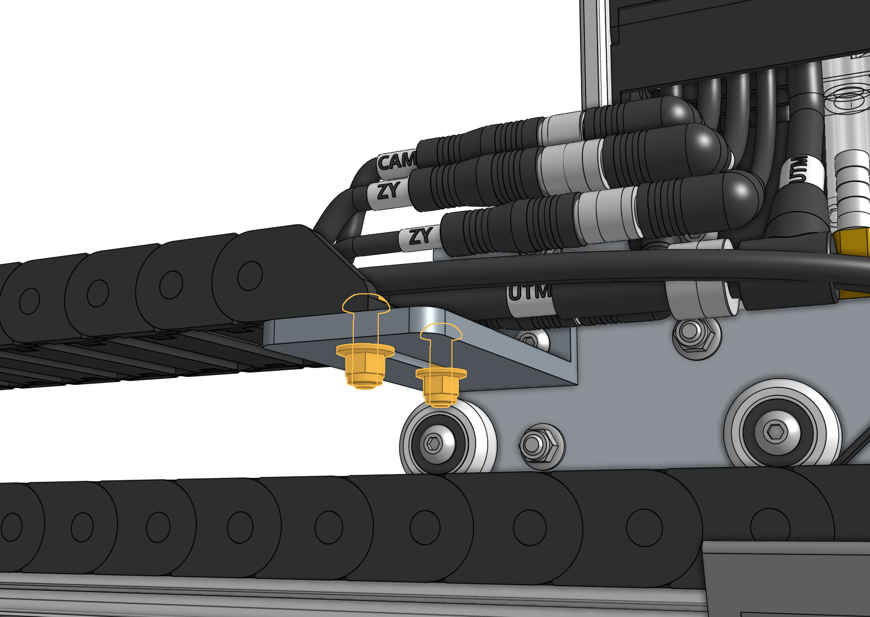
Lay the y-axis cable carrier onto the 60mm horizontal cable carrier supports on the gantry main beam such that the end with the 90-degree connectors will connect to the cross-slide. Attach the cable carrier to the 80mm cable carrier mount using two M5 x 16mm screws and M5 flange locknuts. The screws should thread firmly through the cable carrier end piece.
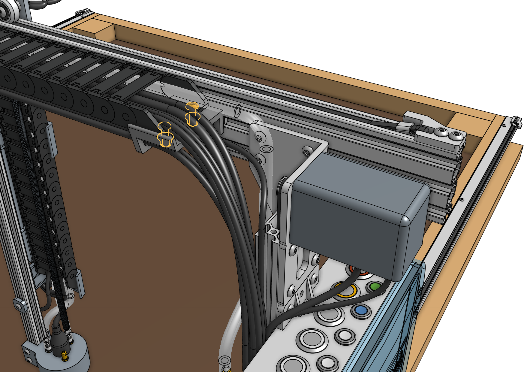
Attach the y-axis cable carrier to the 60mm horizontal cable carrier support nearest the electronics box using two M5 x 16mm screws and M5 flange locknuts. The screws should thread firmly through the cable carrier end piece.
Step 5: Connect the tubing
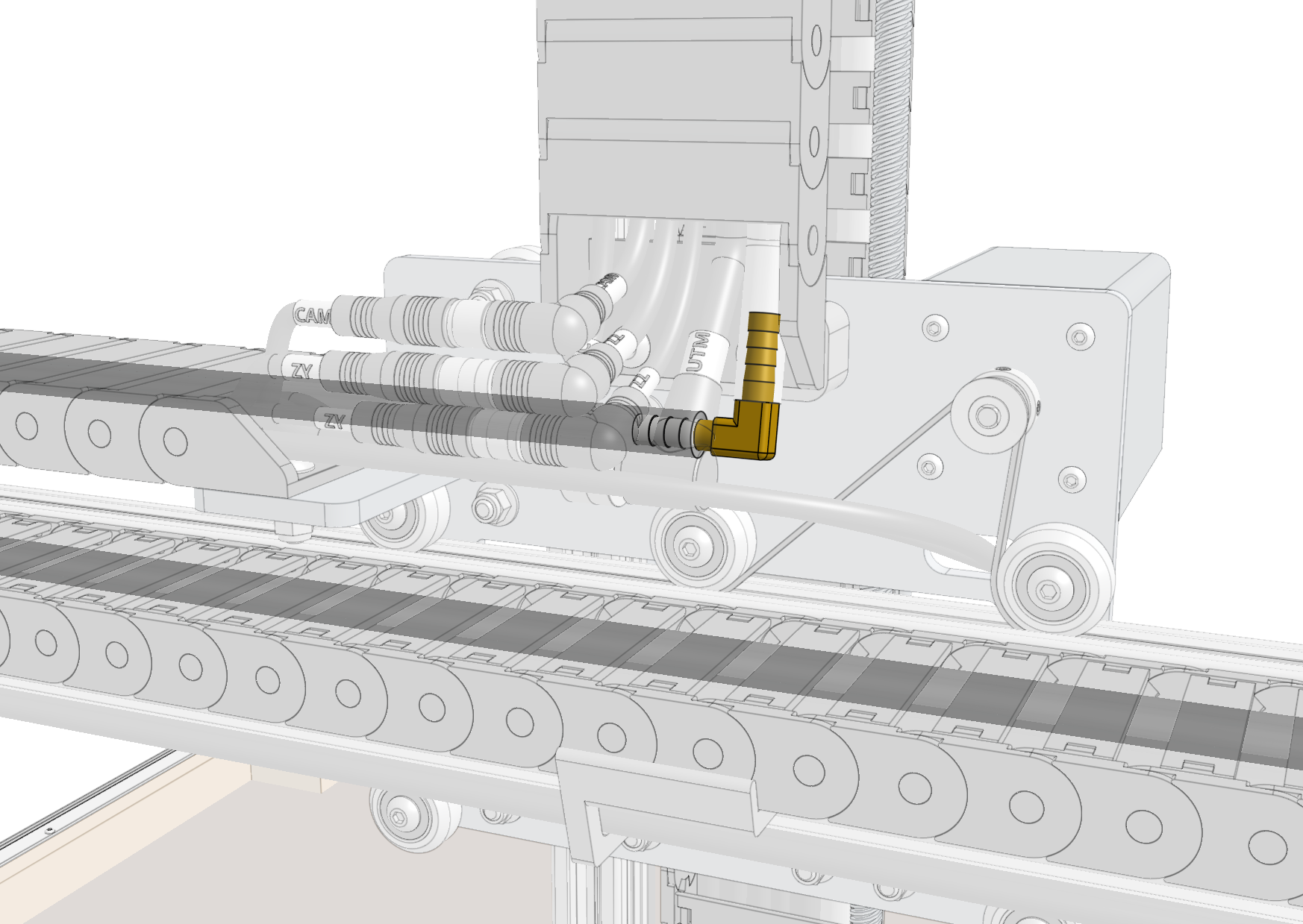
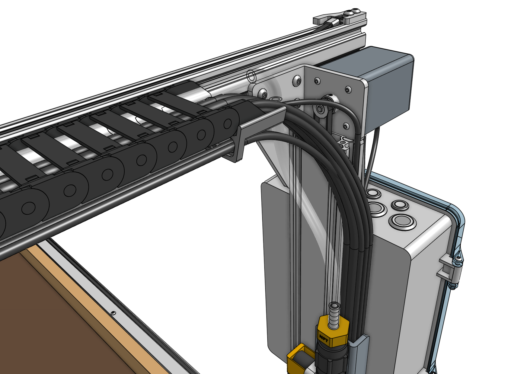
Push the y-axis water tube onto the 90-degree barb and the NPT to barb adapter on top of the solenoid valve.

Step 6: Connect the cabling
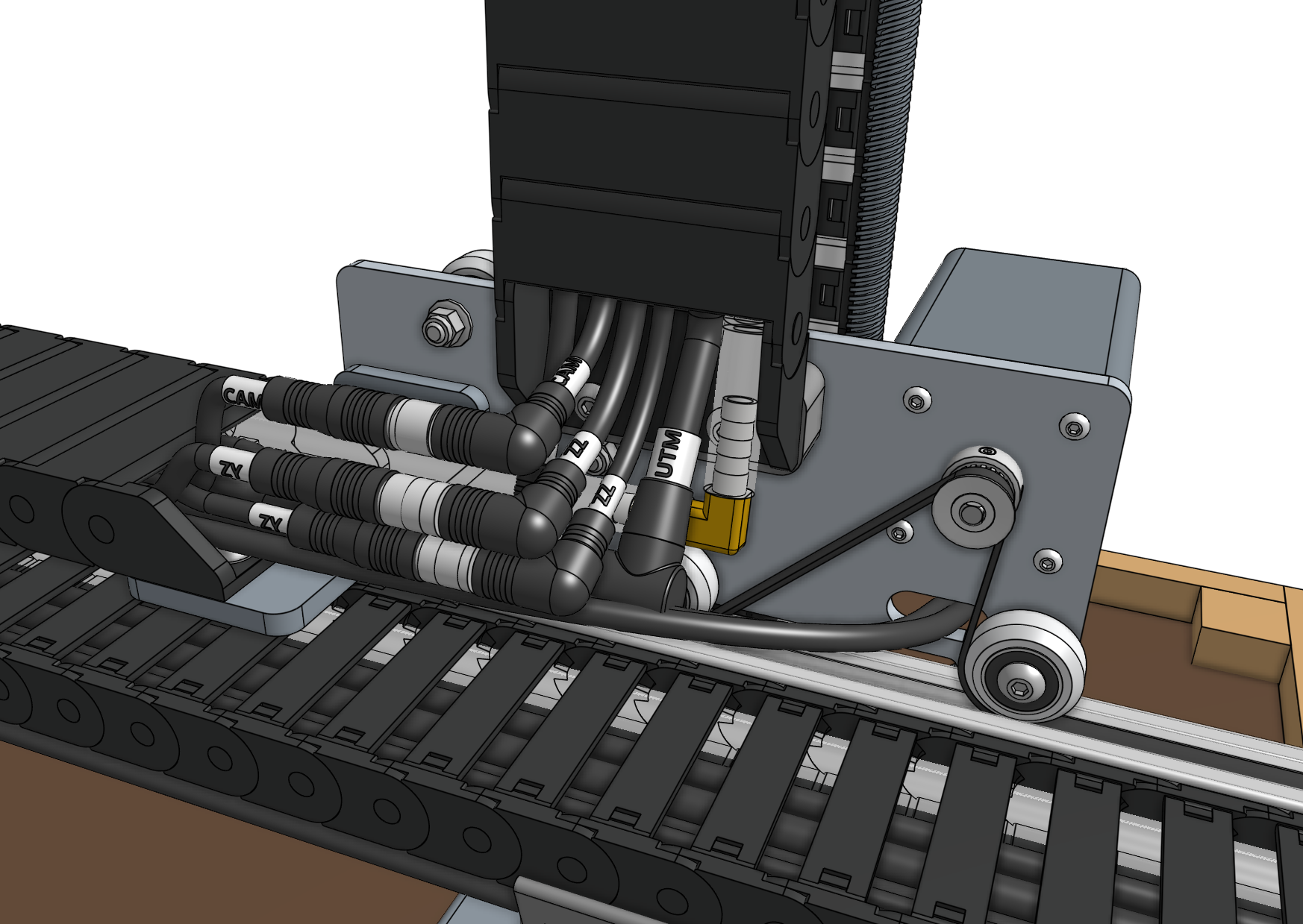
Connect the z-axis and y-axis sections of the following cables together:
- Z vacuum pump cable (
VAC) to Y vacuum pump cable (VAC) with the 4-pin connectors - Z UTM cable (
UTM) to Y UTM cable (UTM) with the 12-pin connectors
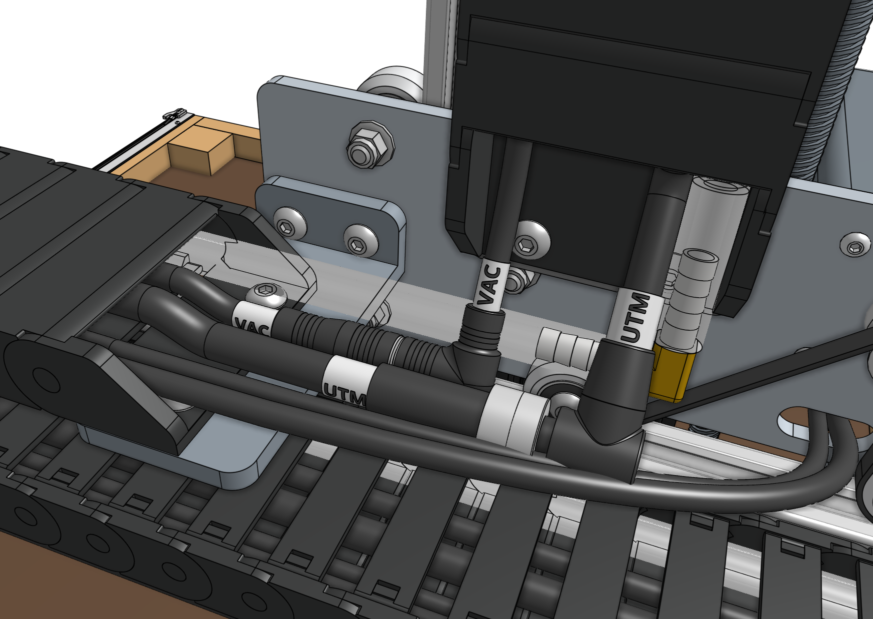
Connect the z-axis and y-axis sections of the following cables together:
ZZencoder cable toZYencoder cable with the 7-pin connectorsZZmotor cable toZYmotor cable with the 4-pin connectors- Camera (
CAM) to camera cable (CAM) with the 4-pin connectors
Some cables use the same 4-pin connectors
Double check you have connected:
CAMtoCAMVACtoVACZYtoZZ
Take your time. A mistake here could cause damage to the electronics.
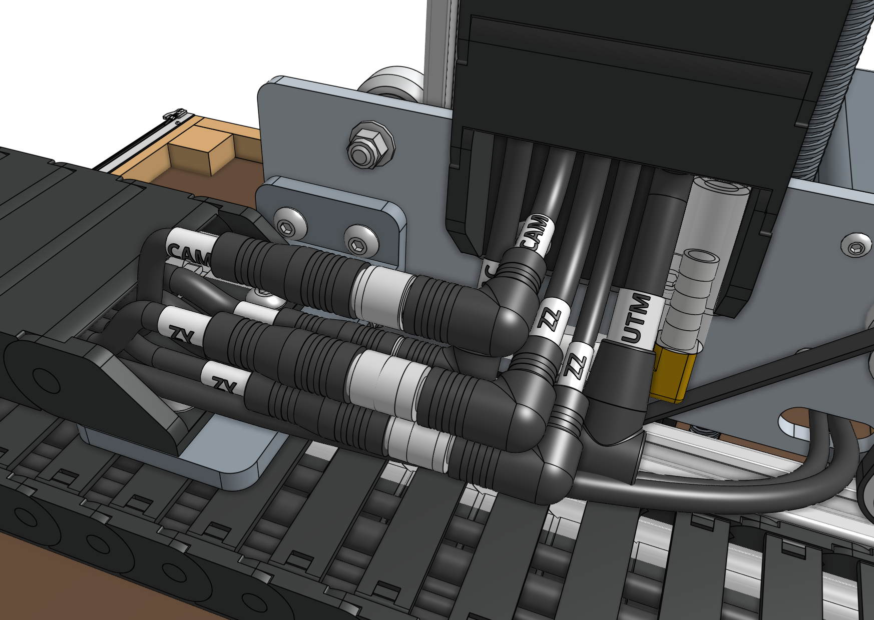
Ensure you fully inserted the 90-degree connectors together. This may require a multi-step process of pushing together, slightly tightening the thumb screws, pushing together again, and tightening some more.
Step 7: Connect the y-axis motor and encoder
Connect the Y motor cable and Y encoder cable to the y-axis motor and encoder.
Use zip ties and plenty of slack to ensure the motor and encoder wires do not rub against the belt.
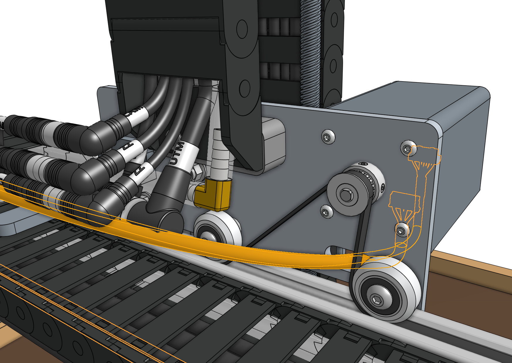

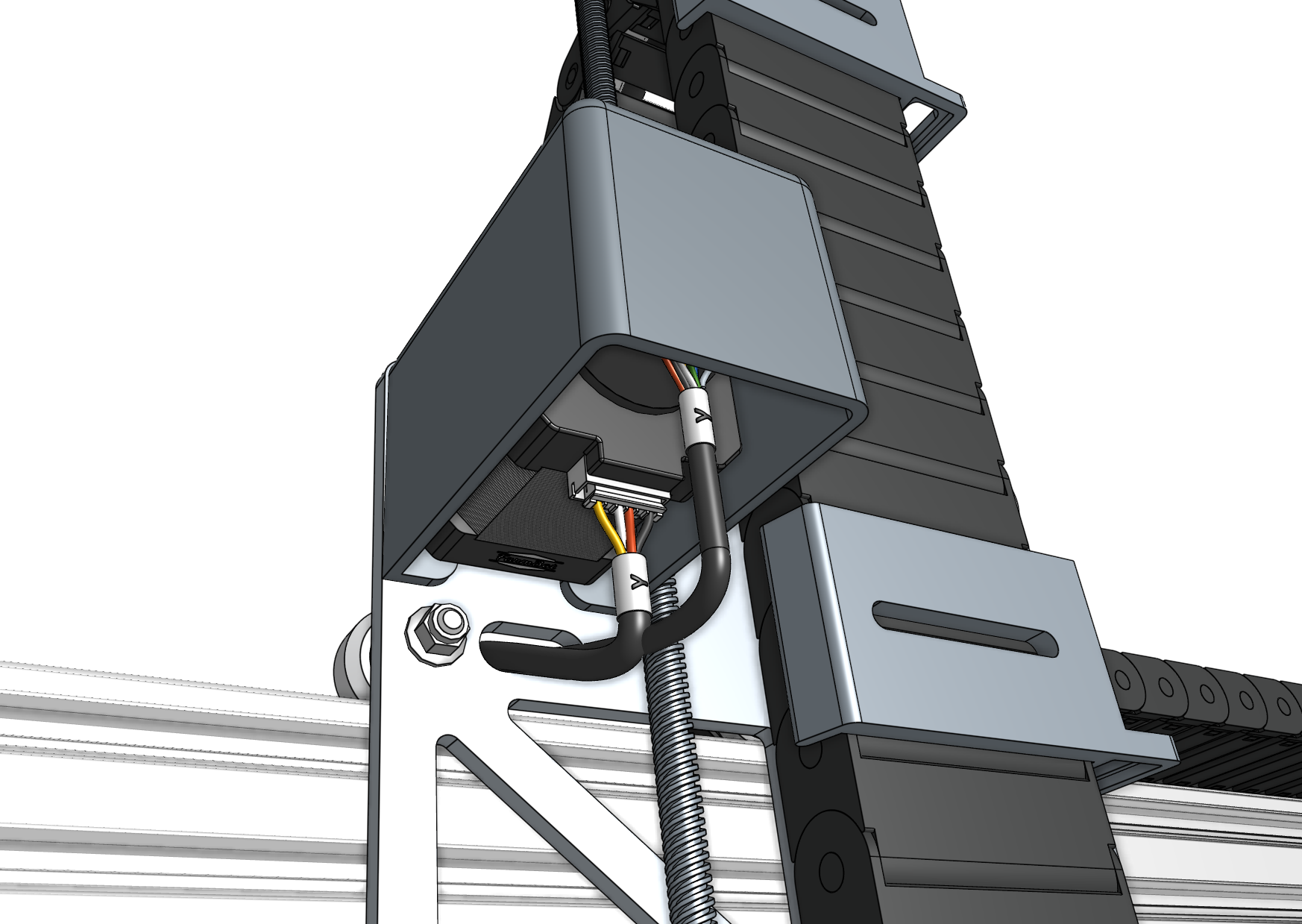
Step 8: Remove slack
Reduce the amount of extra tubing and wiring between the y-axis cable carrier and the z-axis cable carrier by gently pulling any extra cable or tubing length through the y-axis cable carrier. It can be difficult to coax the contents around the bend of the cable carrier, so take your time and ensure that you are not pulling anything too hard.
Never pull any cables by their connectors.
