Gantry
Documentation and assembly instructions for the FarmBot Genesis gantry
- Step 1: Slide the columns onto the tracks
- Step 2: Assemble the main beam
- Step 3: Attach the cable carrier supports
- Step 4: Attach the main beam
- Step 5: Connect the X2 motor and encoder cables
- Step 6: Install the LED light strip
- Step 7: Feed the belts
- Step 8: Secure the belts
- Step 9: Attach the cable carrier
- Step 10: Connect the tubing
- Step 10: Attach the seed trough holder
- What’s next?
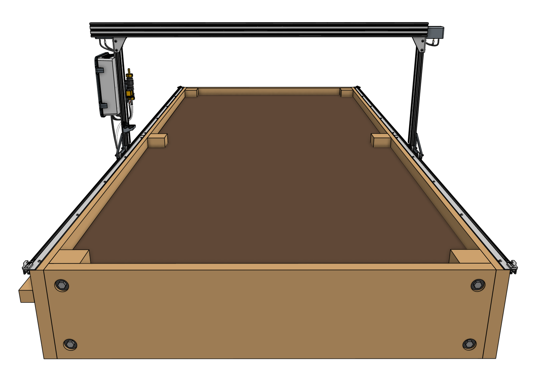
1 to 1.5 hours
This is the estimated time it will take to assemble the gantry.
Step 1: Slide the columns onto the tracks
The eccentric spacers on the lower two V-wheels of each gantry wheel plate are used for making fine adjustments to the spacing between the lower wheels and the upper wheels. Adjusting this spacing is the key to having your gantry move smoothly and wobble-free across the tracks.
If the spacing is too little, then the gantry will not fit onto the tracks at all or be tough to move. If the spacing is too great, then the gantry will be wobbly and loose.
Adjust the eccentric spacers
Adjust the eccentric spacers according to the eccentric spacer adjustment guide.
Once the spacers have been adjusted, slide the gantry columns onto the tracks. The direction that the wheel plates extend from the column is towards the front of FarmBot. Meanwhile, the gantry column with the electronics box should be on the left side of the supporting infrastructure that includes the wood cable carrier supports.
Step 2: Assemble the main beam
This step applies to XL kits only
If you have a standard sized Genesis kit (1.5m wide), proceed to the next step.
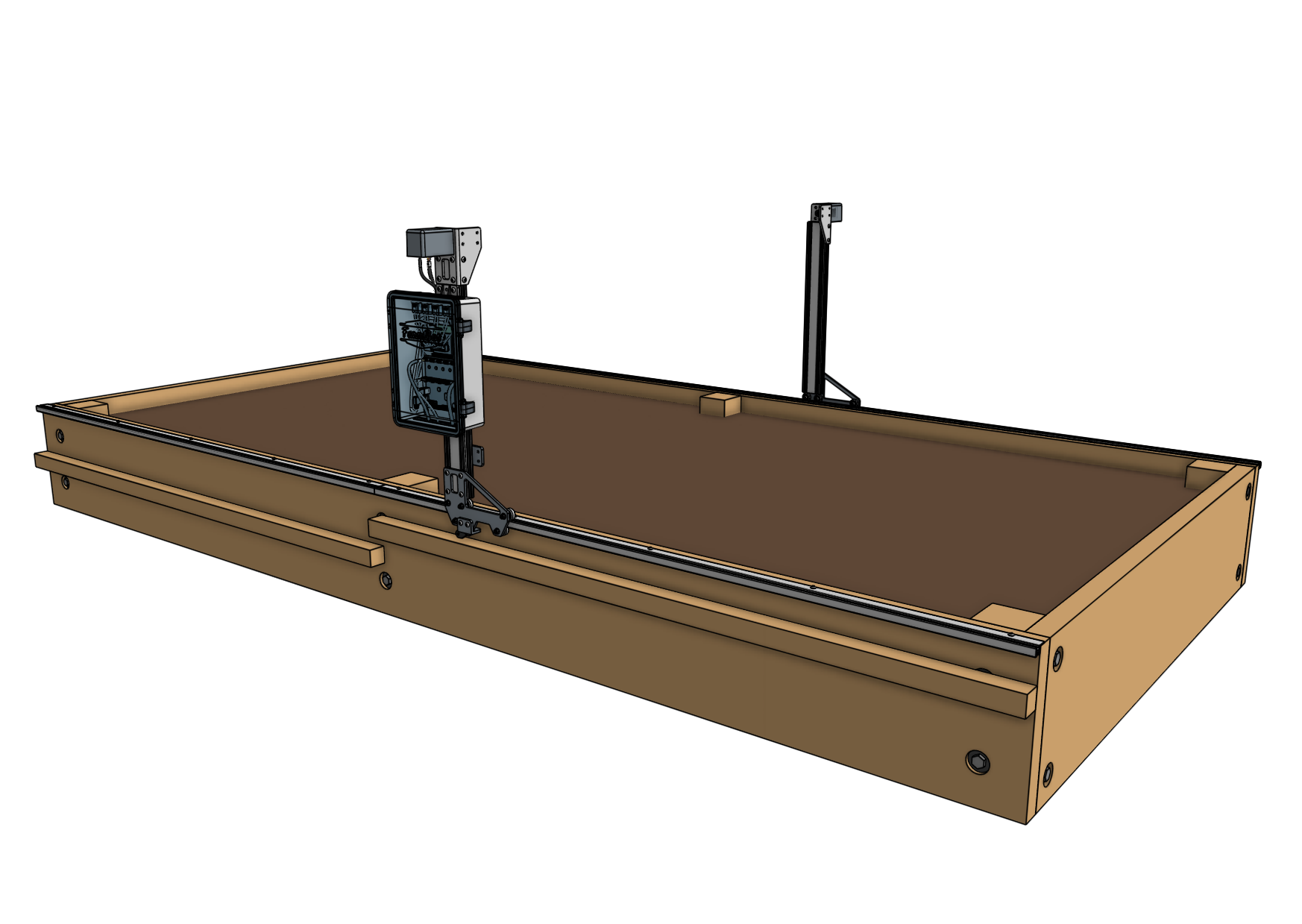
Place both gantry main beams on a flat surface such as a table or patio. Using two 140mm nut bars and eight M5 x 10mm screws, attach the gantry joining bracket to the lower two slots of both extrusions. The notch in the middle of the bracket should be aligned with the joint between the two extrusions.
Step 3: Attach the cable carrier supports
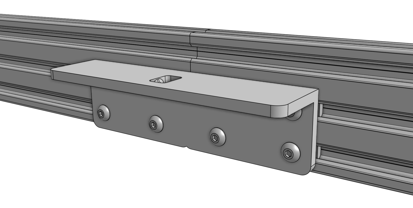
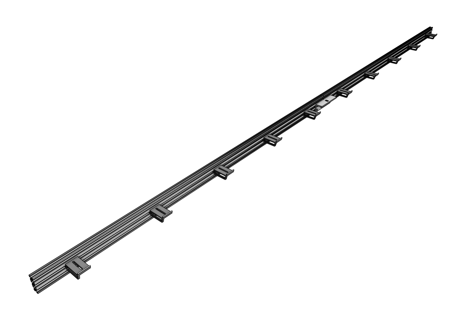
Using M5 x 10mm screws and 40mm nut bars, attach five 60mm horizontal cable carrier supports to the middle slot of the gantry main beam extrusion. For Genesis kits, there is only one main beam extrusion, so only five supports will be used.
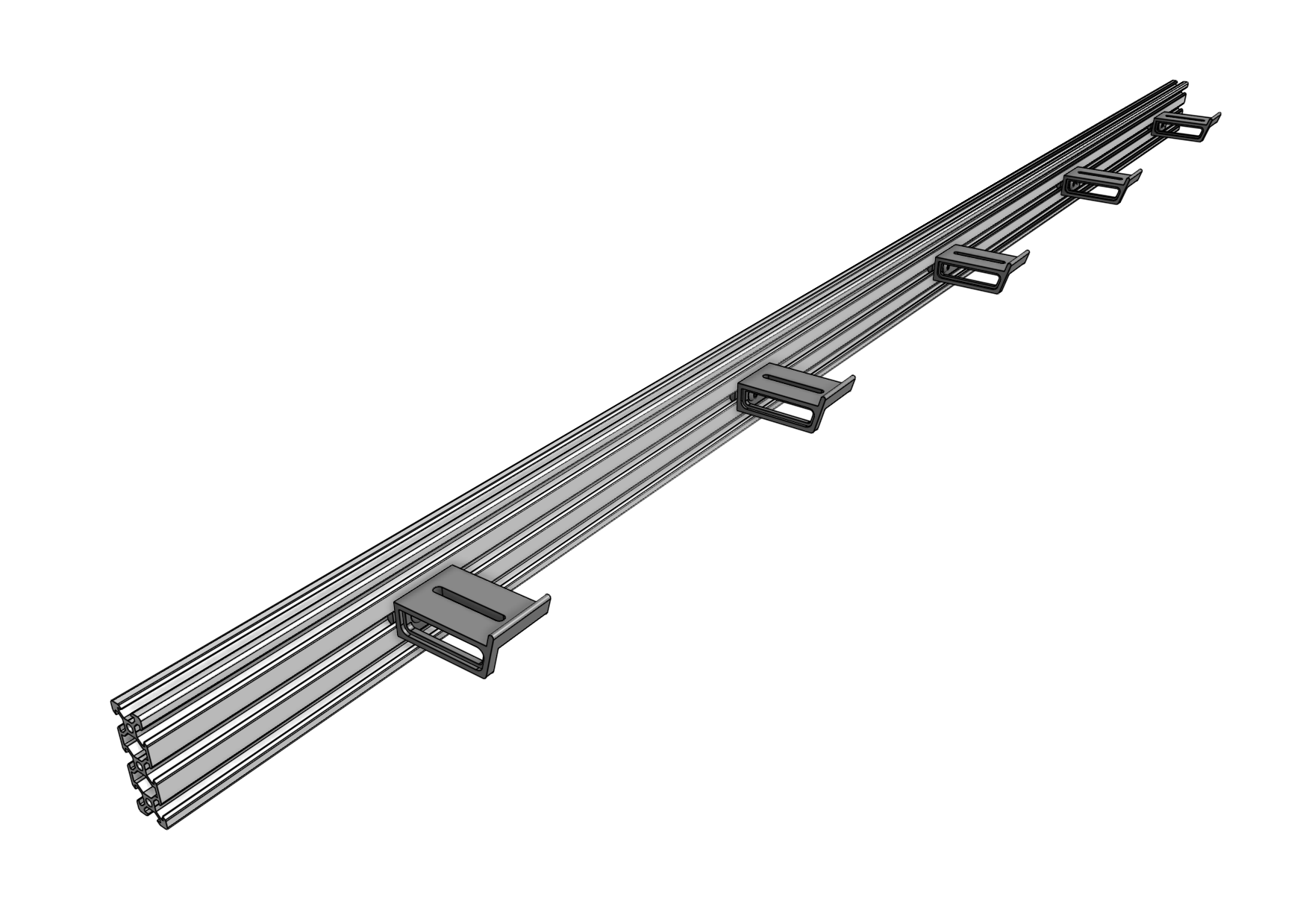
For Genesis XL kits, there are two main beam extrusions, so 10 supports will be used, and they should be positioned on the same side of the extrusions as the gantry joining bracket.
Step 4: Attach the main beam
Grab a friend
The next step requires an additional person to complete.
Lift up the gantry main beam and position it onto the front of the gantry corner brackets. The cable carrier supports should be on the same side of the main beam as the gantry corner brackets. Slide a 60mm nut bar into each end of the lowest two extrusion slots and use M5 x 10mm screws to loosely attach the main beam to the corner brackets.
The gantry main beam should be positioned as follows:
- The top face of the main beam should be 20mm above the top edges of the gantry corner brackets.
- The end of the main beam on the electronics box side should extend beyond the horizontal motor housing by at least 10mm or 0.5”. If you built your supporting infrastructure to the maximum width, then the main beam should not be extended any further than this.
- The other end of the main beam (opposite the electronics box) can extend beyond the right gantry corner bracket by any amount. If you have built your supporting infrastructure to the maximum width, then the main beam will not extend at all beyond the corner bracket.
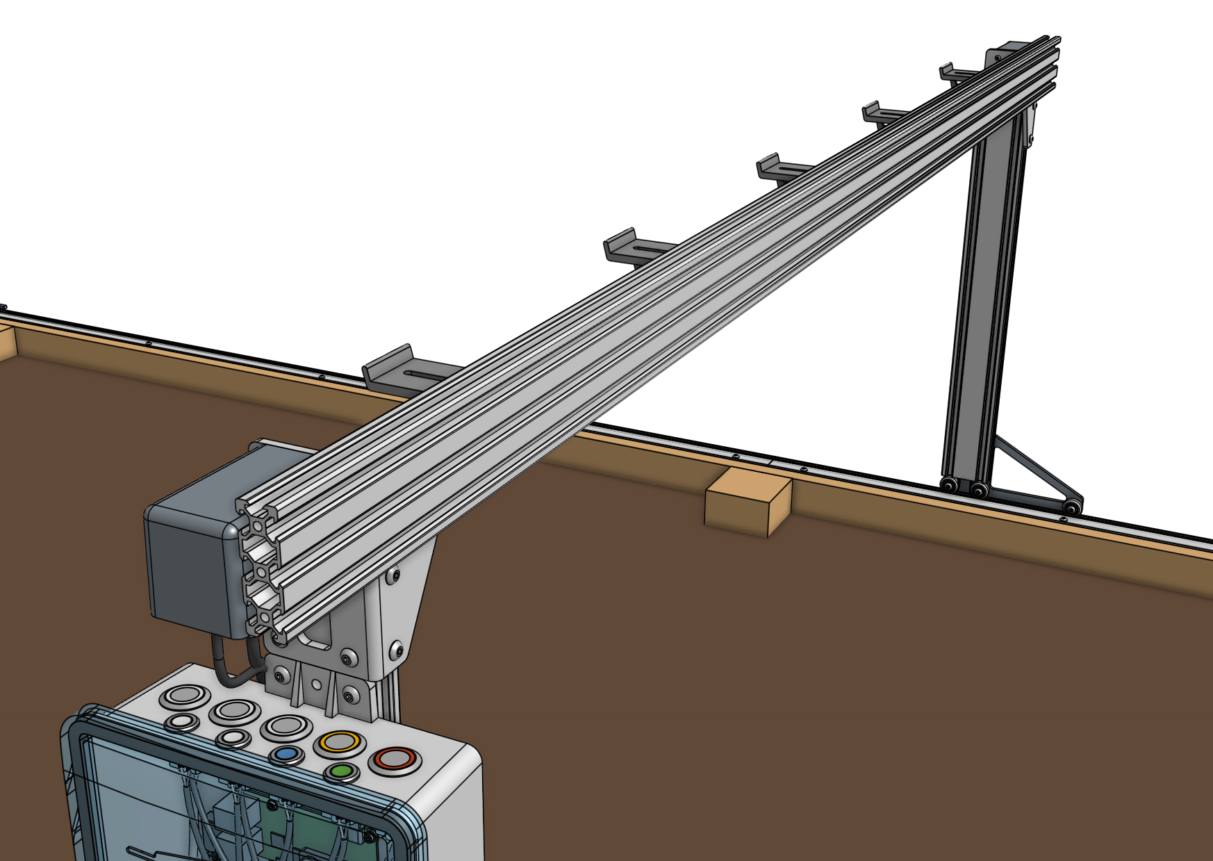

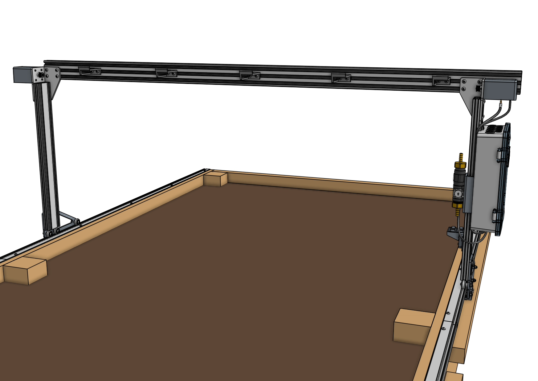
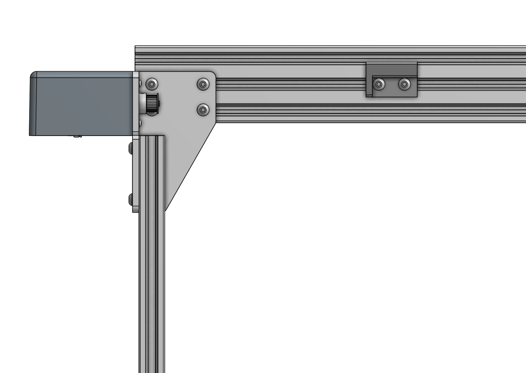
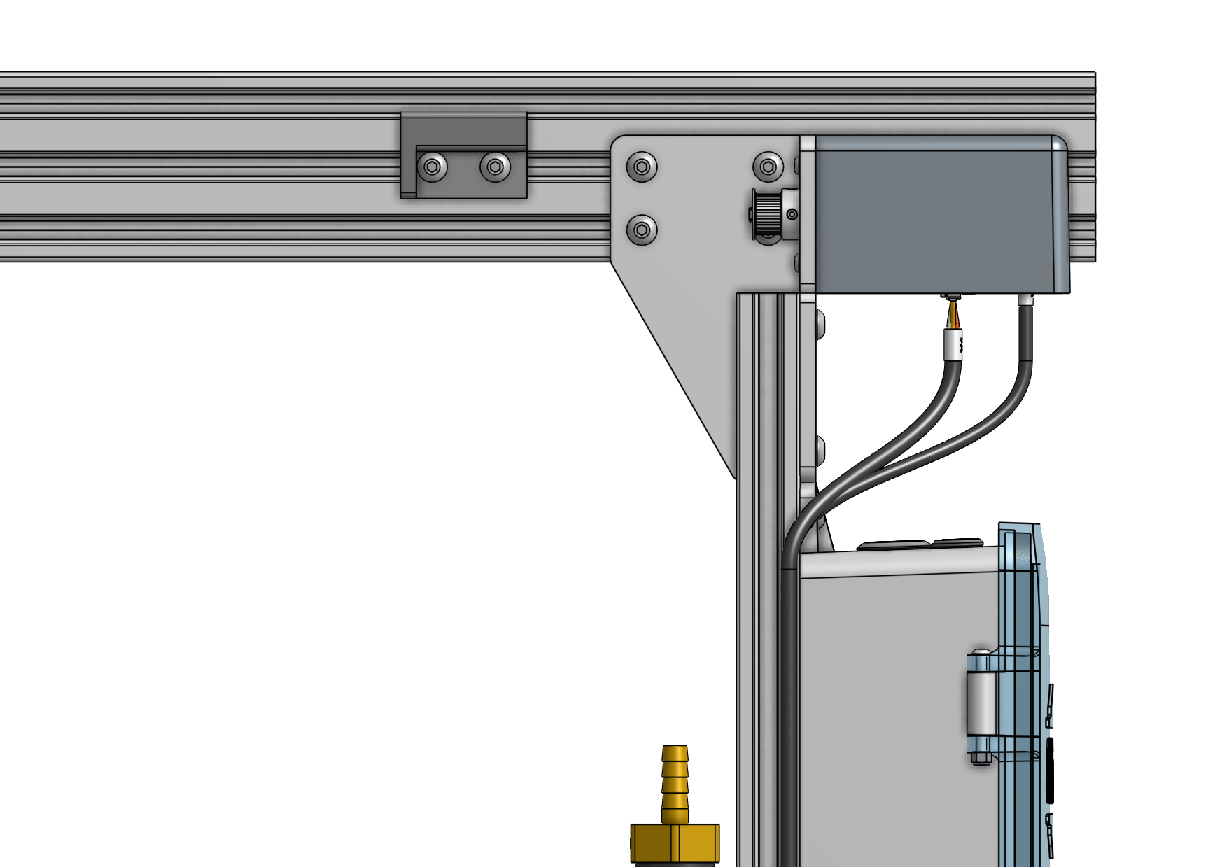
Ensure that the gantry columns are vertical and form a 90 degree angle with the main beam. Then tighten the M5 x 10mm screws.
The main beam will not necessarily be centered on the supporting infrastructure. This is OK.
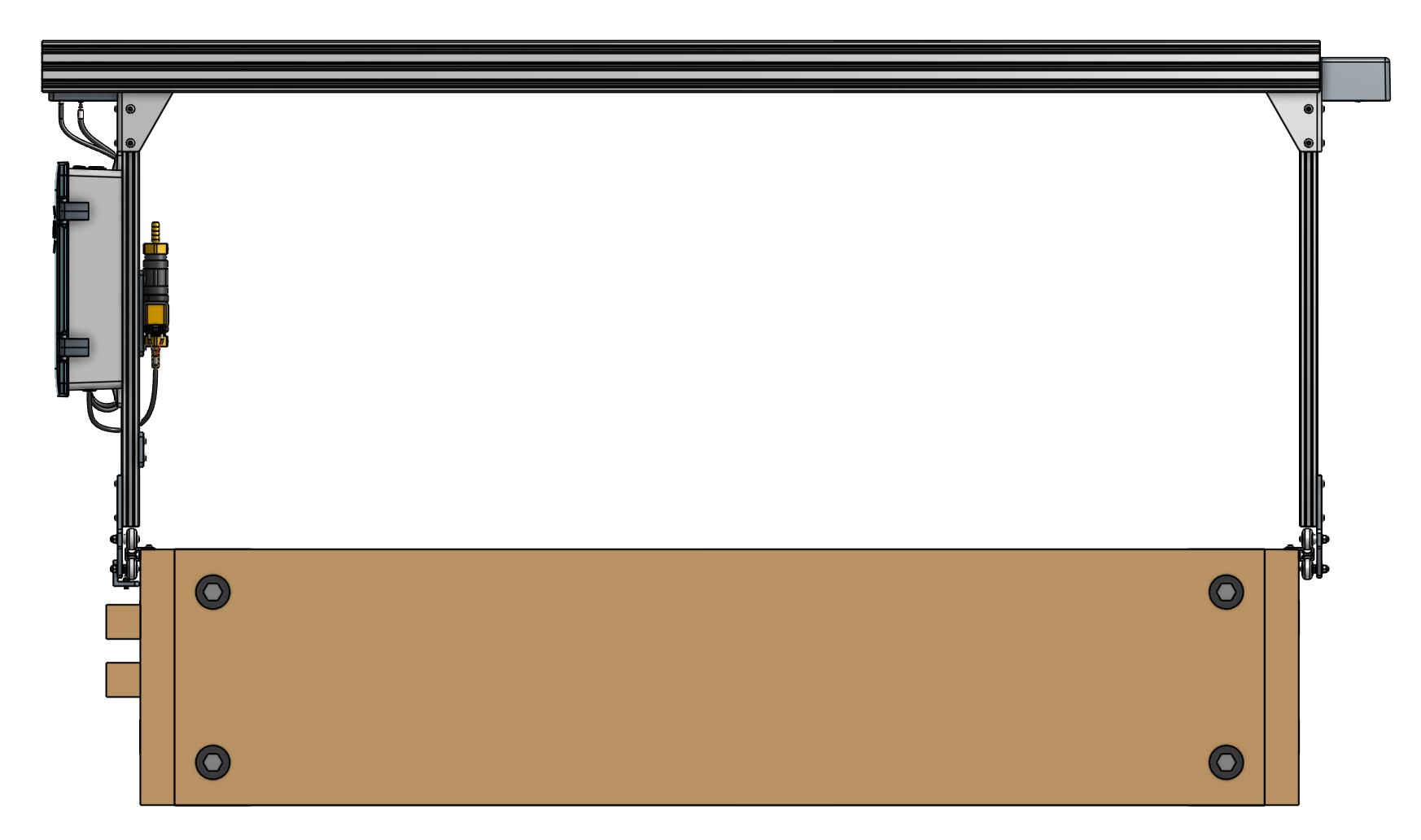
Step 5: Connect the X2 motor and encoder cables
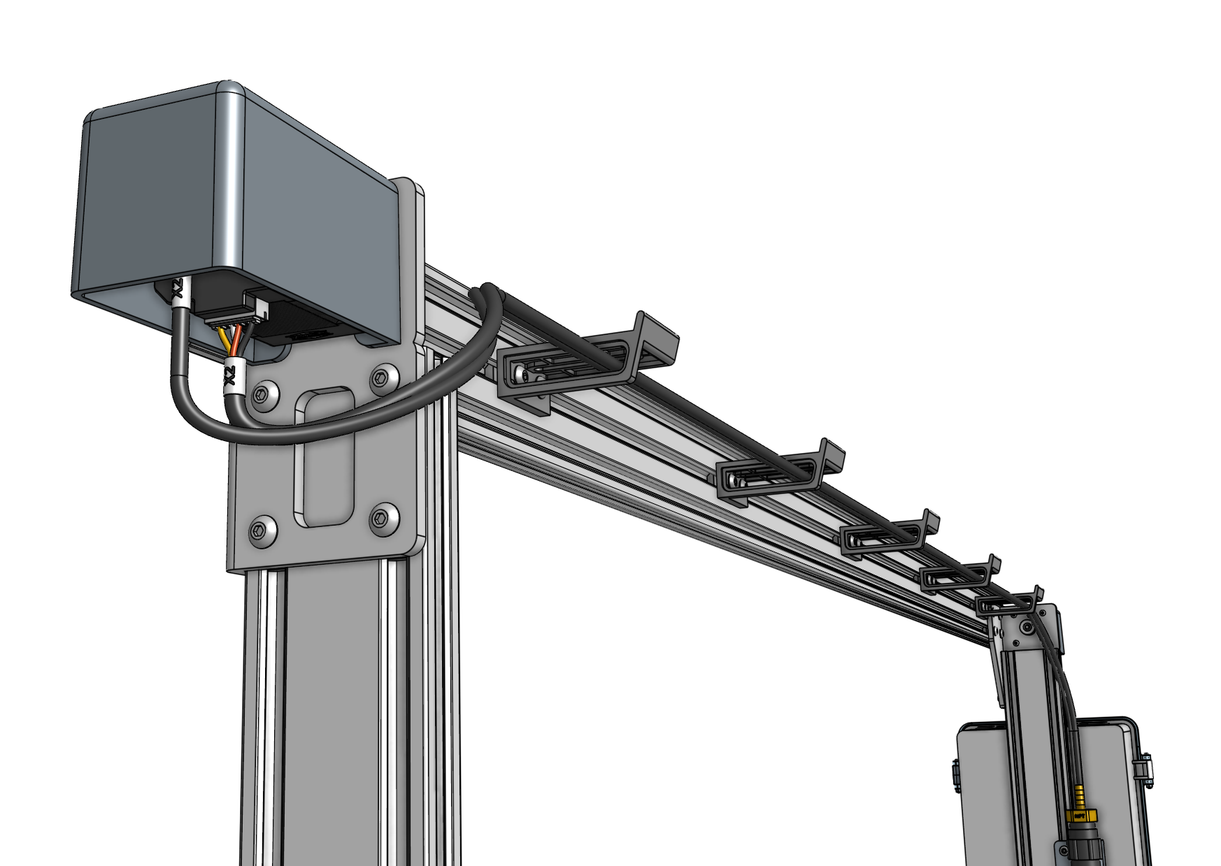
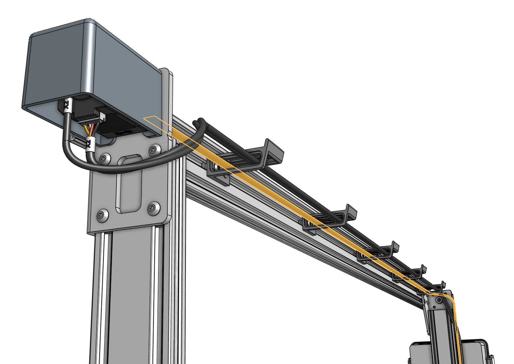
Connect the X2 motor cable and X2 encoder cable to the X2 motor and encoder (located on the side opposite the electronics box). Then route the cables through the slots in all of the 60mm horizontal cable carrier supports along the gantry main beam.
You will plug the cables into the electronics box in a few steps from now.
Step 6: Install the LED light strip
Route the LED strip (highlighted orange in the image below) through the 60mm horizontal cable carrier supports on the gantry main beam. The end with the connector should be positioned near the electronics box. You can secure the strip to the first and last cable carrier supports using 100mm zip ties.
You will plug the LED strip into the electronics box in a few steps from now.
Step 7: Feed the belts
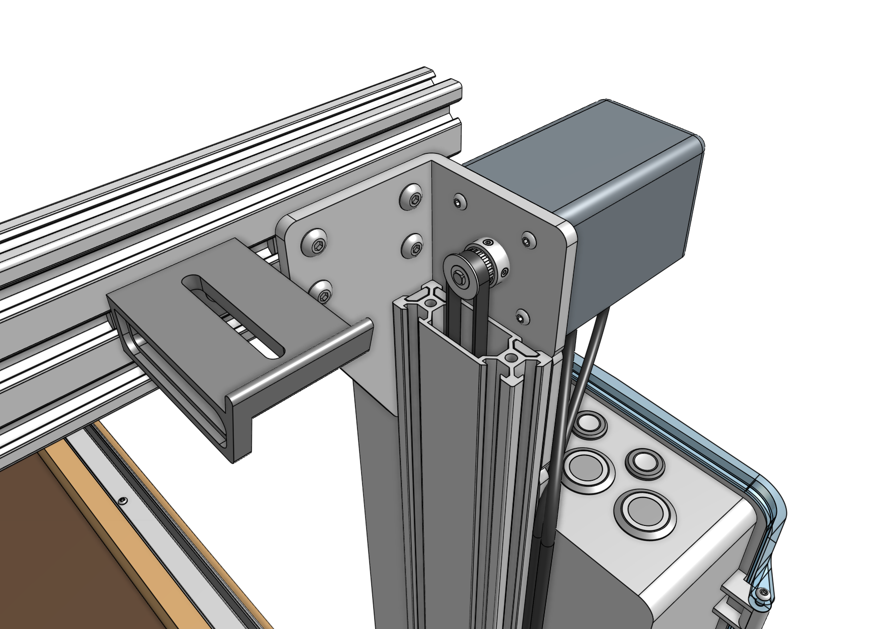
Drop the ends of one of the longer belts down the large opening in a gantry column, ensuring that the belt teeth engage the pulley.
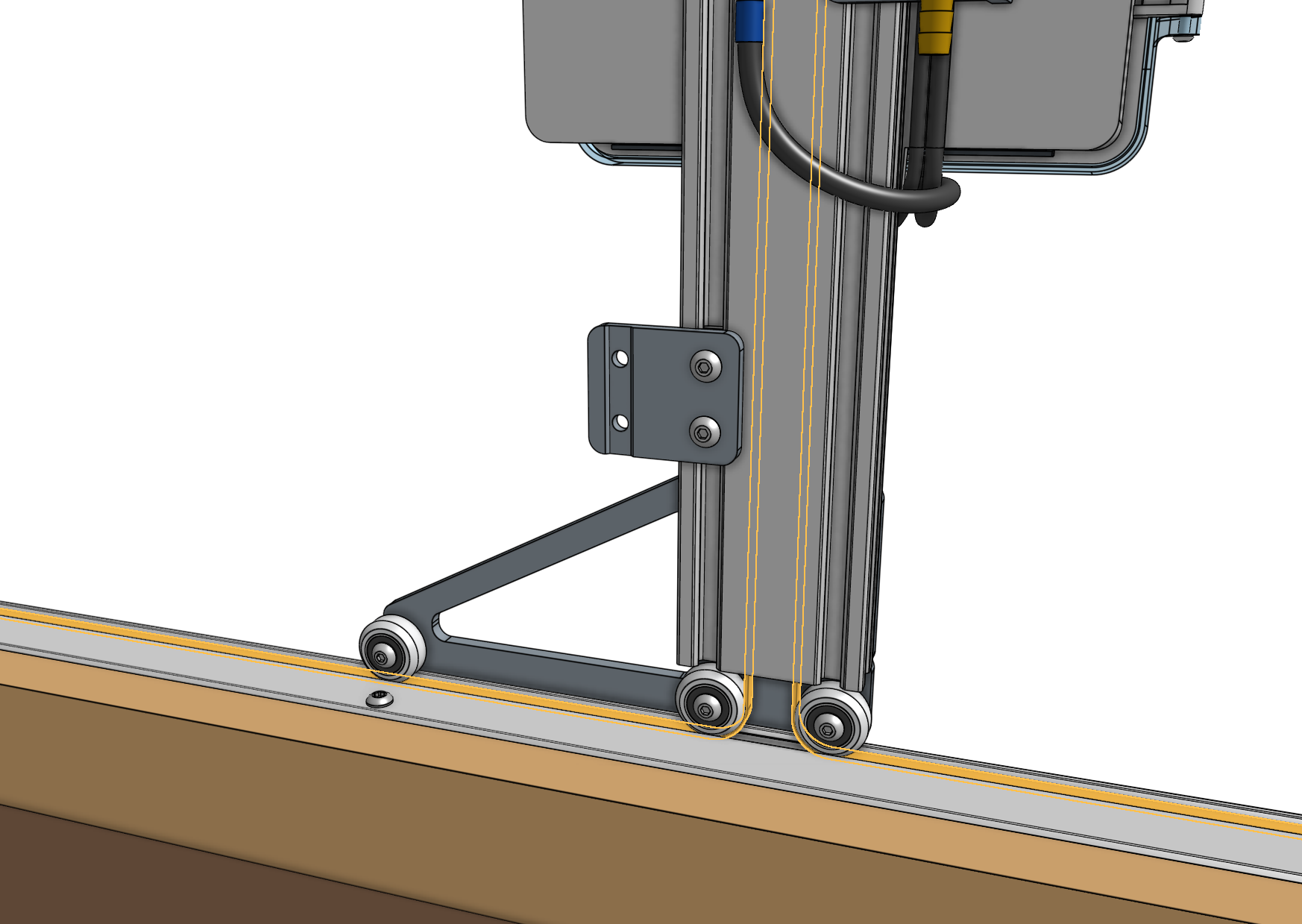
Grab the ends of the belt at the bottom of the gantry column and feed them under the V-wheels of the gantry wheel plate, then along the top of the track extrusions to the ends of the tracks. The flat side of the belt should be in contact with the V-wheels.
Avoid twists
When dropping the belt ends through the gantry column and feeding them along the tracks, ensure that there are no twists in the belt.
Step 8: Secure the belts
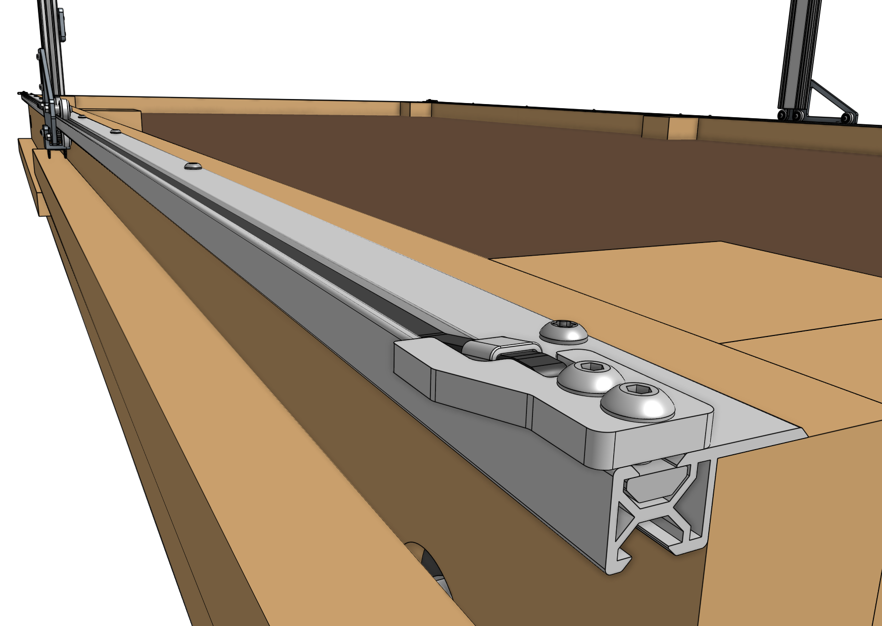
Secure one end of the belt to the tracks by using a belt clip, belt sleeve, 20mm nut bar, and two M5 x 10mm screws. The belt must be wrapped through the clip as outlined in the belt installation guide, with the tab of the belt clip extending over the outside of the bed. Repeat for the other end of the belt on the other end of the tracks.
Trim any extra belt length if desired.

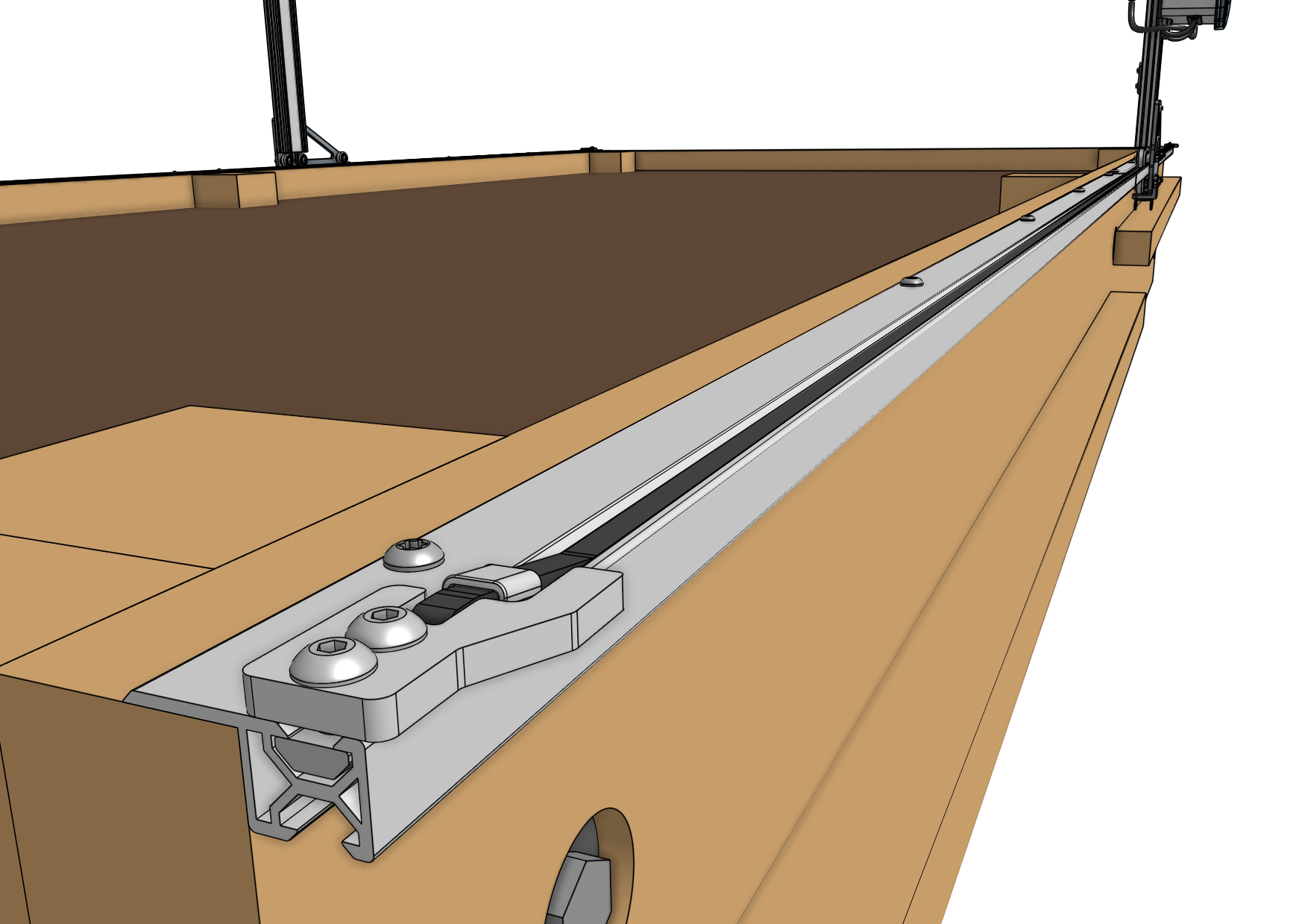
Repeat steps 7 and 8 for the second x-axis belt on the other side of the FarmBot.
Step 9: Attach the cable carrier
Lay the x-axis cable carrier onto the supporting infrastructure’s wood cable carrier support. Connect the end of the cable carrier without an end piece to the end piece that is pre-mounted on the bottom of the left gantry column.
It is easier to connect the cable carrier by pushing it into the end piece at an angle, engaging the first circular hinge point, and then straightening the cable carrier to engage the second hinge point. Ensure both hinge points are snapped in all the way.
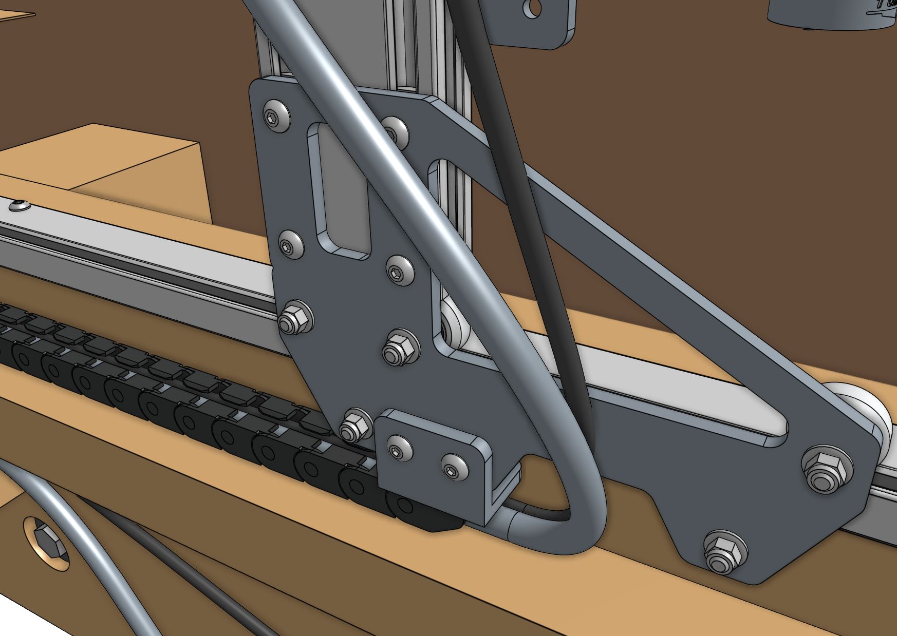
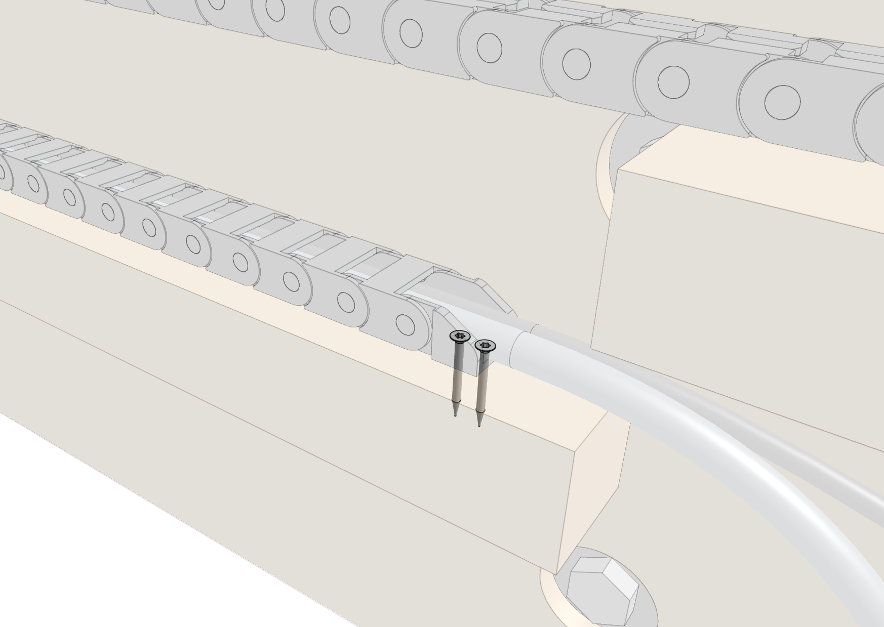
Fasten the other end of the cable carrier to the wood cable carrier support using two T10 flathead wood screws.
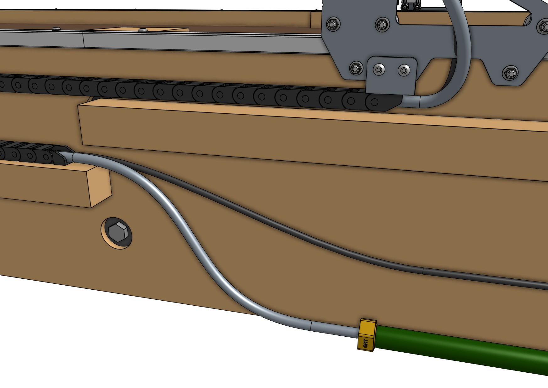
Step 10: Connect the tubing
Push the water tube coming from the x-axis cable carrier onto the lower NPT to barb adapter beneath the solenoid valve.
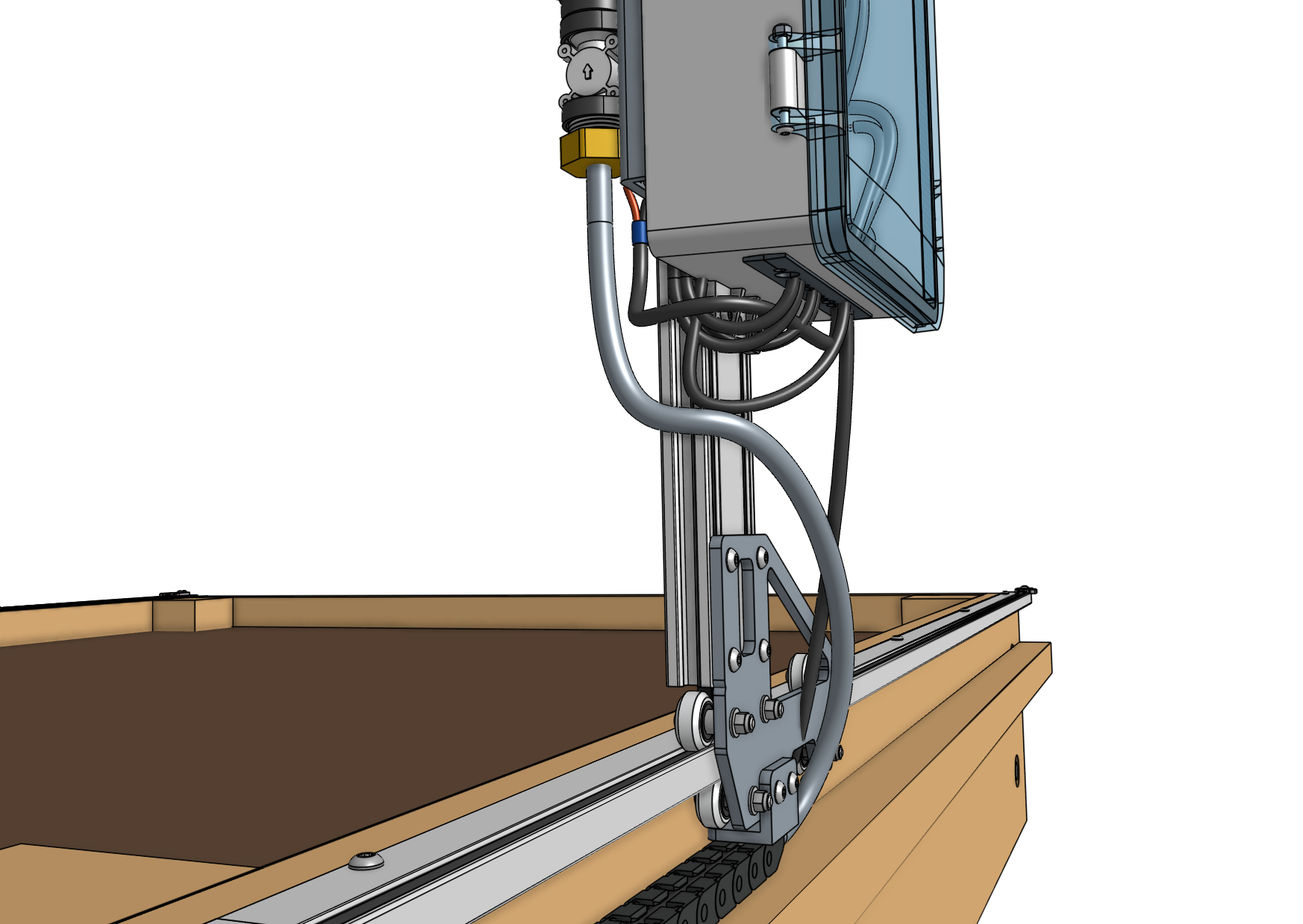
Screw the garden hose to barb adapter onto the garden hose. Then push the water tube coming from the bottom of the x-axis cable carrier onto the barb.
You will need to provide a garden hose of the appropriate length to connect FarmBot to your municipal water source - one is not provided with the FarmBot kits.
Step 10: Attach the seed trough holder
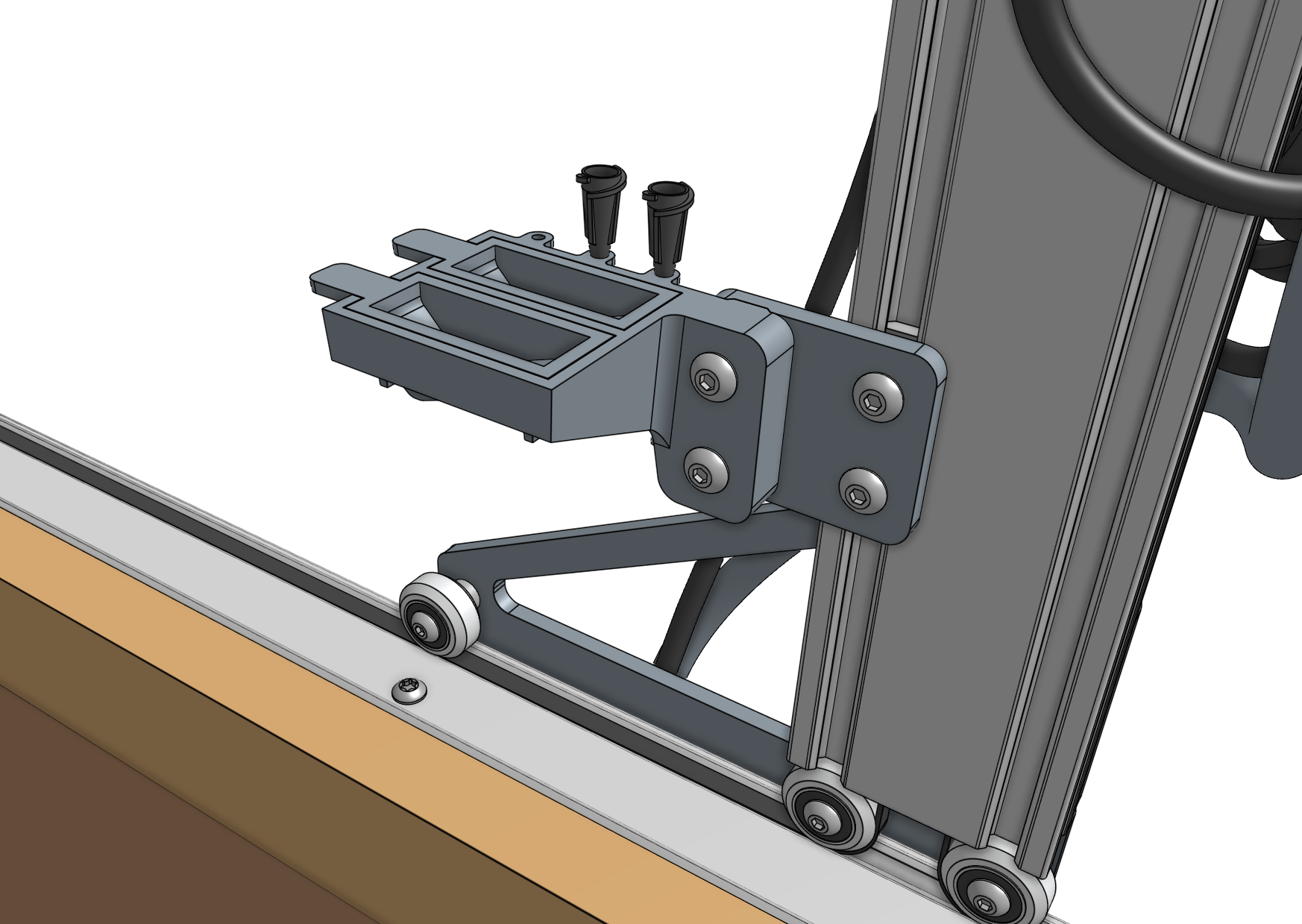
Attach the seed trough holder to the seed trough holder mount using two M5 x 30mm screws and M5 flange locknuts. Then place the two seed troughs into the holder. Optionally, you may store up to three luer lock needles in the holder as well.
