Plug Everything In
- Step 1: Attach the RAMPS power cable to the power supply
- Step 2: Attach the Raspberry Pi power cable to the power supply
- Step 3: Connect the peripherals
- Step 4: Plug in the stepper motors and rotary encoders
- Step 5: Plug in the UTM cable’s connectors
- Step 6: Add the power cord to the power supply
- Step 7: Set the power supply input voltage
- Step 8: Plug in the power supply
- Step 9: Keep power supply in outdoor box
- What’s next?
Step 1: Attach the RAMPS power cable to the power supply
The power supply should still be unplugged and unpowered at this time.
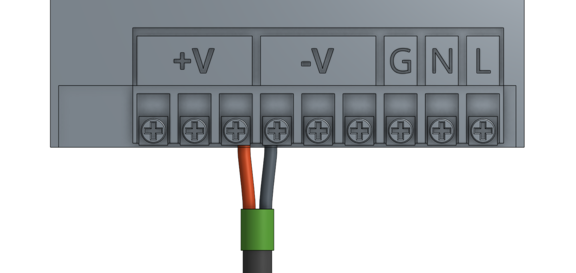
Attach the red (positive) wire from the RAMPS power cable to one of the available positive outputs on the power supply and tighten the screw.
Attach the black (negative) wire from the RAMPS power cable to one of the available negative outputs on the power supply and tighten the screw.
Step 2: Attach the Raspberry Pi power cable to the power supply
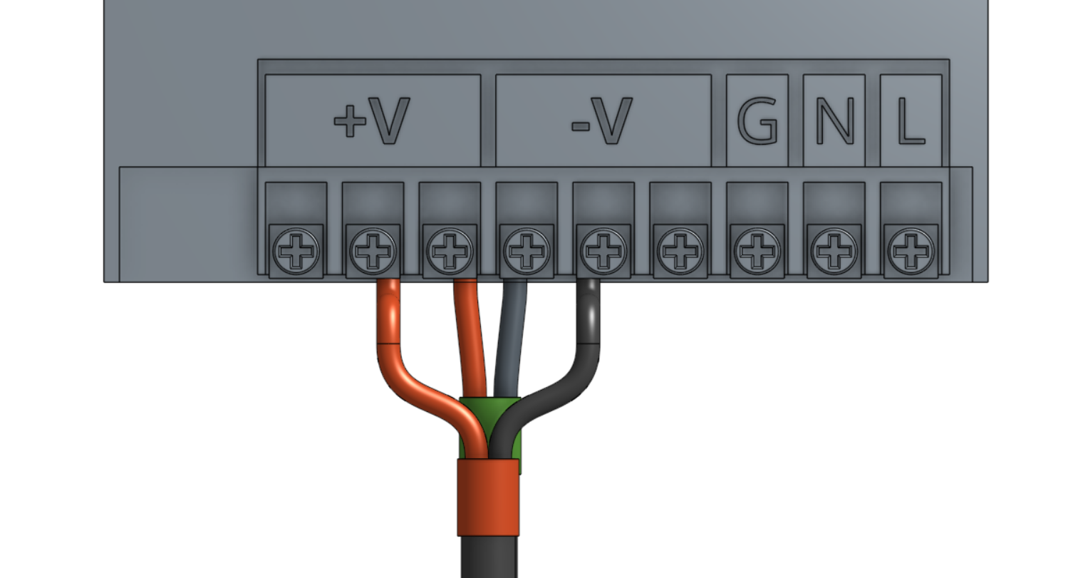
Attach the red (positive) wire from the Raspberry Pi power cable to one of the available positive outputs on the power supply and tighten the screw.
Attach the black (negative) wire from the Raspberry Pi power cable to one of the available negative outputs on the power supply and tighten the screw.
Step 3: Connect the peripherals
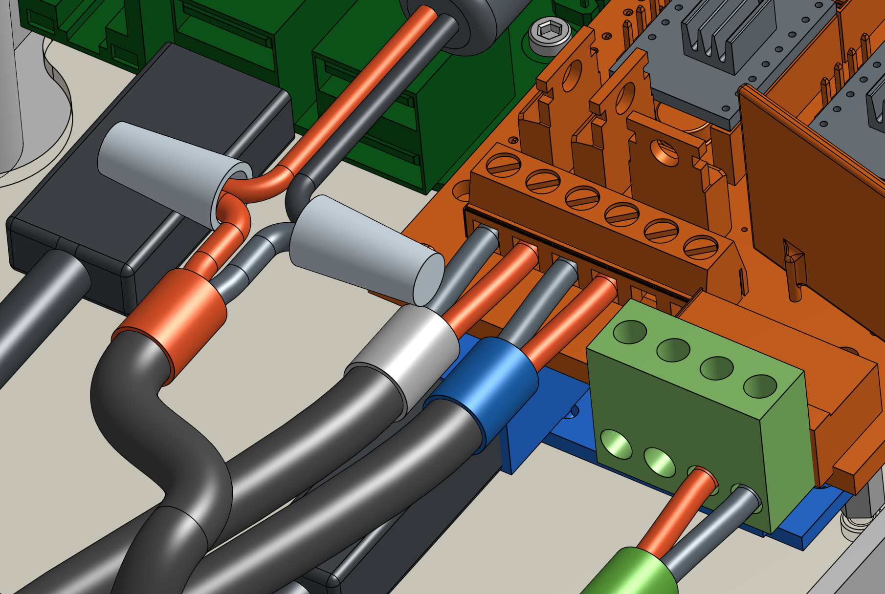
Connect the solenoid valve cable to the positive and negative terminals labelled D9 on the RAMPS shield.
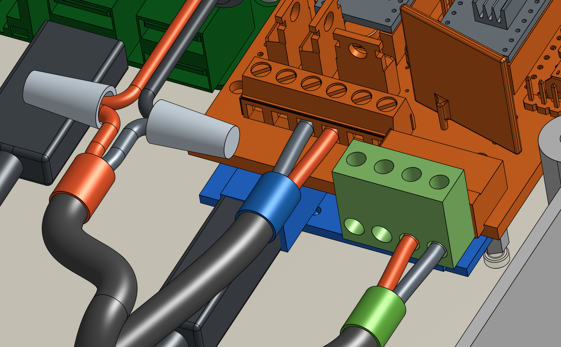
Connect the vacuum pump cable to the positive and negative terminals labelled D10 on the RAMPS shield.
Step 4: Plug in the stepper motors and rotary encoders
Plug in the motor and encoder cables to the RAMPS shield according to the following diagram.
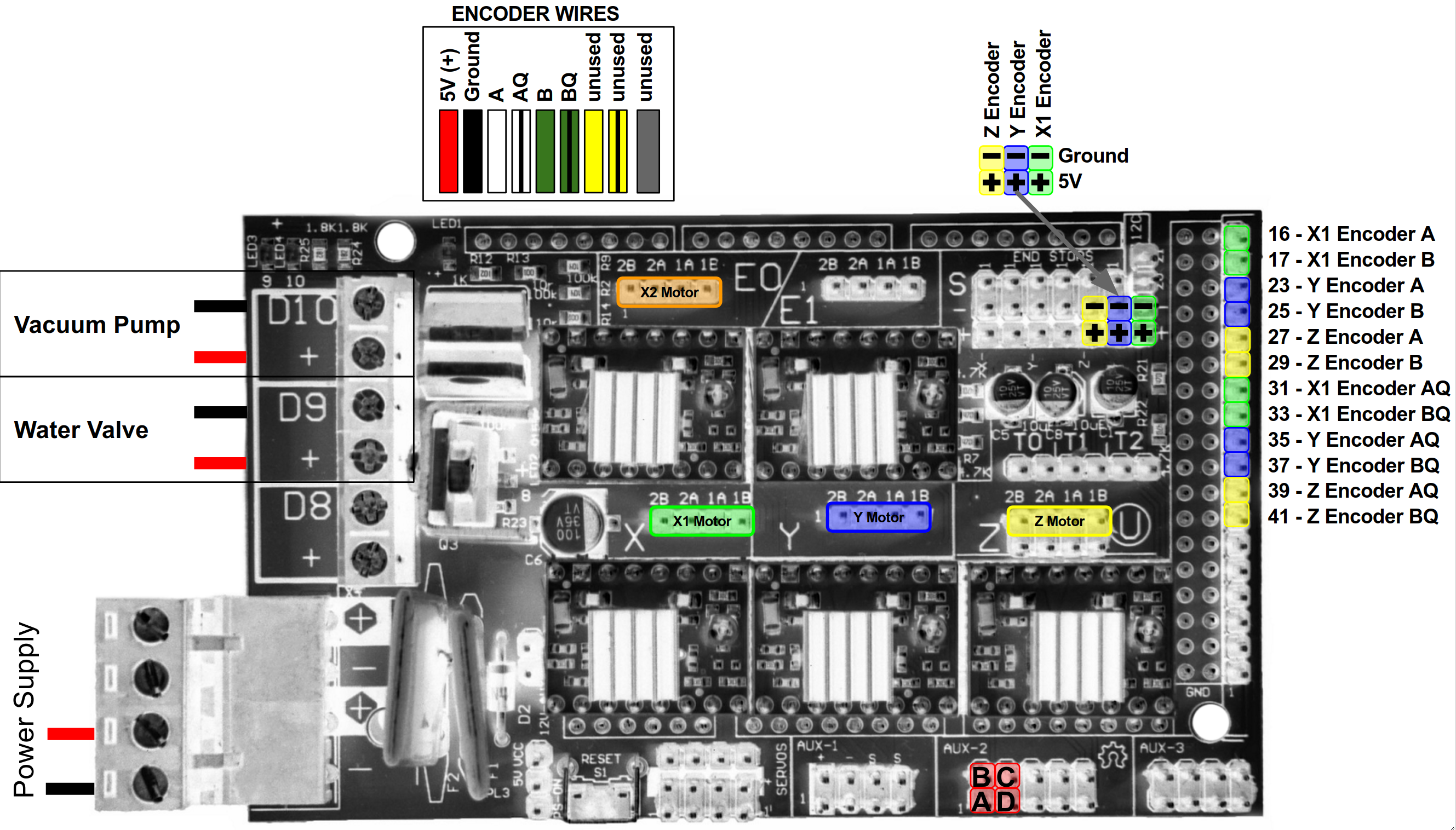
Plugging in the correct black wire
The encoder cables have two black wires. The thinner black wire is the ground wire, which needs to be plugged into the RAMPS board. The slightly thicker black wire is connected to the cable’s shielding, which does not need to be connected to RAMPS.
Motor Cable Orientation
You can plug the stepper motor cables into the RAMPS board in either direction: black-red-white-yellow or yellow-white-red-black top-to-bottom. Changing the direction that the motor wire connector is plugged in will change the direction that the motor moves. So if a motor is moving right when it should be moving left, you can change the orientation of the stepper motor wire connector on the RAMPS board.
Since the X1 and X2 motors need to be moving in opposite directions for the gantry to move, the motor wire connectors for X1 and X2 should be plugged in opposite each other (for example, yellow on top for X1 and yellow on bottom for X2).
Second X-Axis Encoder
Only one x-axis encoder is currently implemented in the firmware, so the X2 encoder wires do not need to be plugged in to the RAMPS board at this time.
Step 5: Plug in the UTM cable’s connectors
Plug in the UTM’s wires to the RAMPS shield according to the pin mapping table.
| UTM Pin/UTM Wire | is connected to | and used for |
|---|---|---|
| A/1 | +5V on Arduino/RAMPS | Soil sensor |
| B/2 | Ground (0V) on Arduino/RAMPS | Ground |
| C/3 | Pin D63 on Arduino/RAMPS - Digital-In | Tool verification |
| D/4 | Pin D59 (A5) on Arduino/RAMPS - Analog-In | Soil sensor and other analog signal tools |
Note
As of the v4.0.0 software released on June 21, 2017, the UTM Pin/Wire A/1 should be connected to +5V on Arduino/RAMPS, while B/2 should be connected to Ground. This change is because the tool verification pin now uses the pull-up resistor in the firmware, so it should be jumped to Ground, instead of +5V. Note: you should double check the wiring of your soil sensor as well.
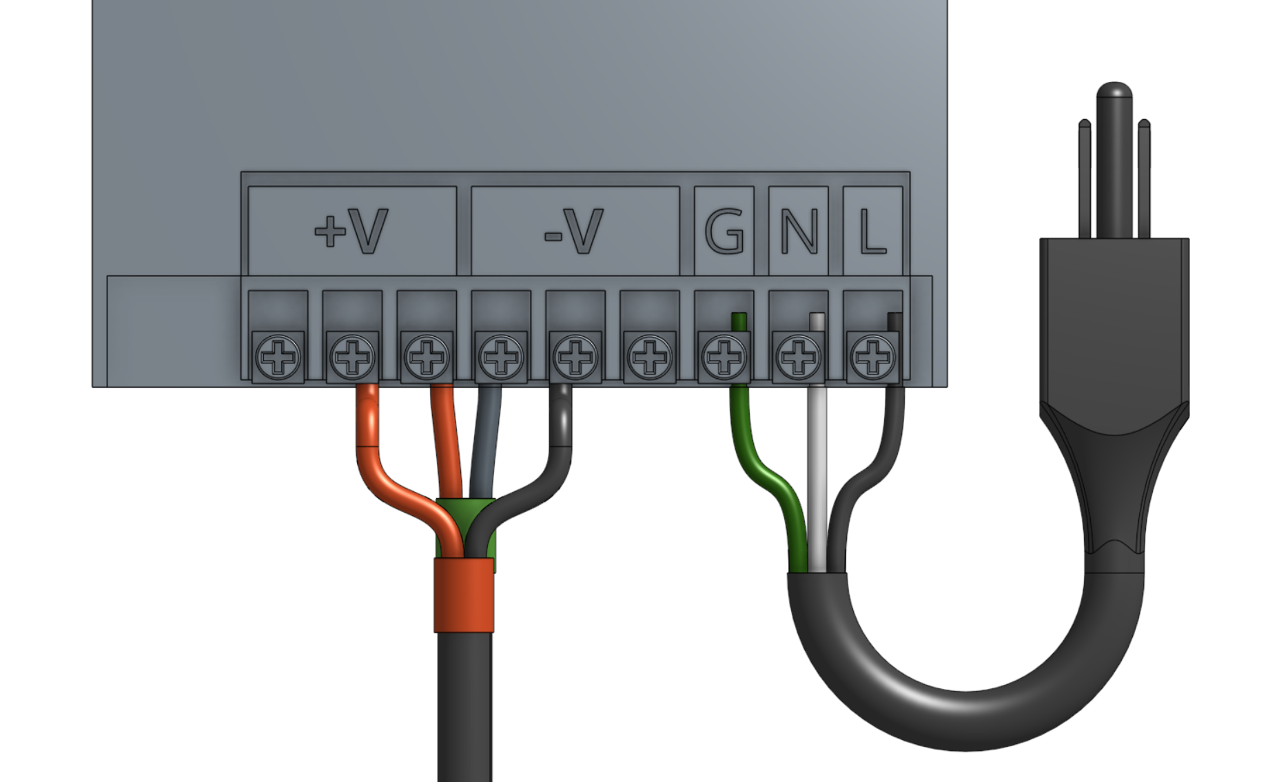
Step 6: Add the power cord to the power supply
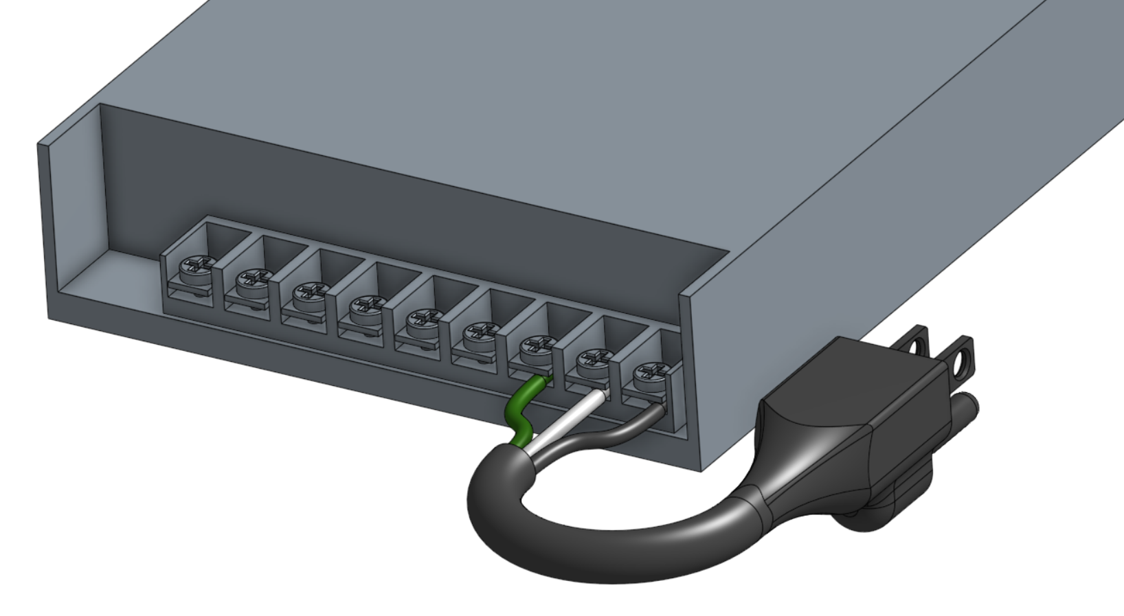
Attach the FarmBot power plug to the power supply inputs according to the following image.

Step 7: Set the power supply input voltage
The power supply can accept both 110V and 220V power input.
Mandatory
You MUST set the power supply’s input voltage switch to the correct setting before you plug it in otherwise you risk destroying the power supply.
Set the switch to the correct input voltage. The voltage label you see must match your country’s power infrastructure.

Step 8: Plug in the power supply
Before plugging in...
Double check all of your connections, component orientations, input voltage switch, and ensure there are not any loose wires that could short circuit.
Beware of electrical shock
Remember that once you plug in the power supply, your system will be powered. Once powered, you cannot add, remove, or change any motor cables, peripheral wires, stepper drivers, etc, or you risk frying your electronics and/or being electrically shocked.
Once powered, be especially careful working around the power supply’s exposed inputs and outputs, and the exposed electronics boards. Do not touch or handle any exposed contacts or other electrical components.
If everything looks good, and you understand the precautions needed around powered electronics, go ahead and plug FarmBot into the wall.
The mark of success
If all has gone well, your Raspberry Pi should boot up and you should revel in the little blinking red and green lights!
Something wrong?
See smoke? Heard a loud pop? If anything seems suspicious or hazardous, immediately unplug the power supply from the wall and contact us at contact@farm.bot.
Need to make changes?
If you need to add, remove, or change any of the wiring now or in the future, you MUST unplug the power supply from the wall first. This will minimize the risk of electrical shock and the potential to permanently damage your electronics.
Step 9: Keep power supply in outdoor box
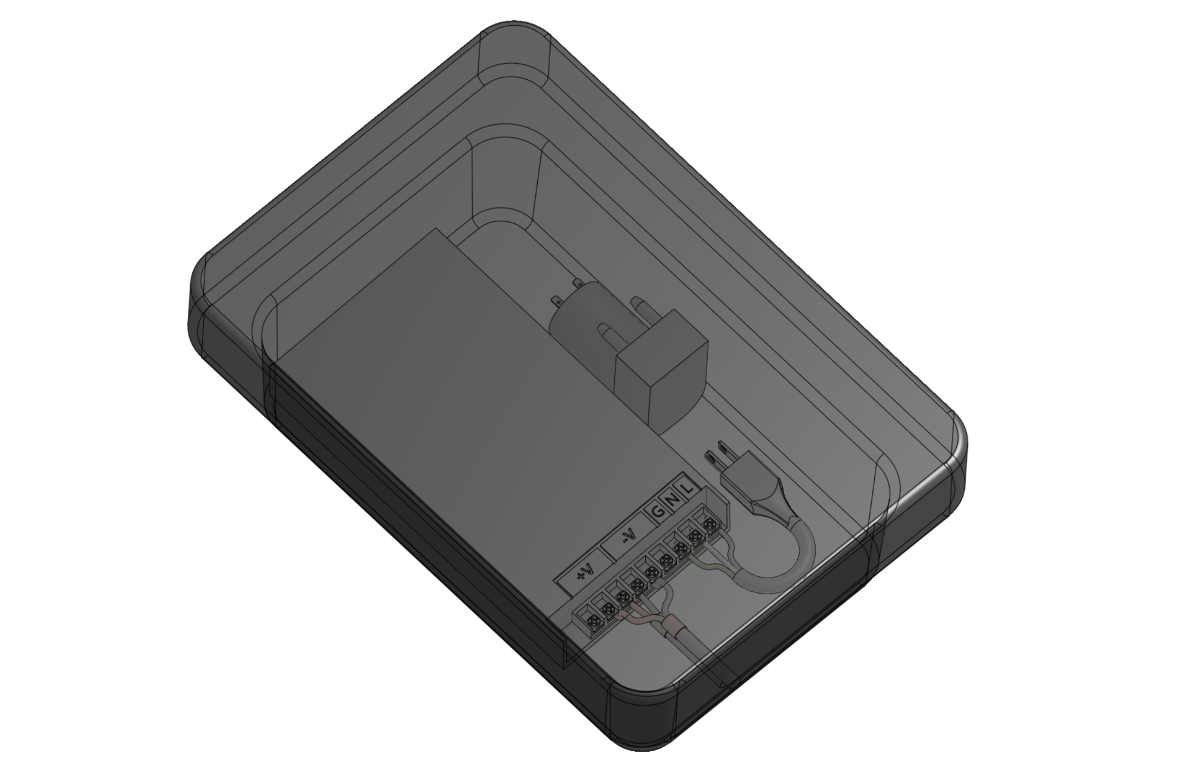
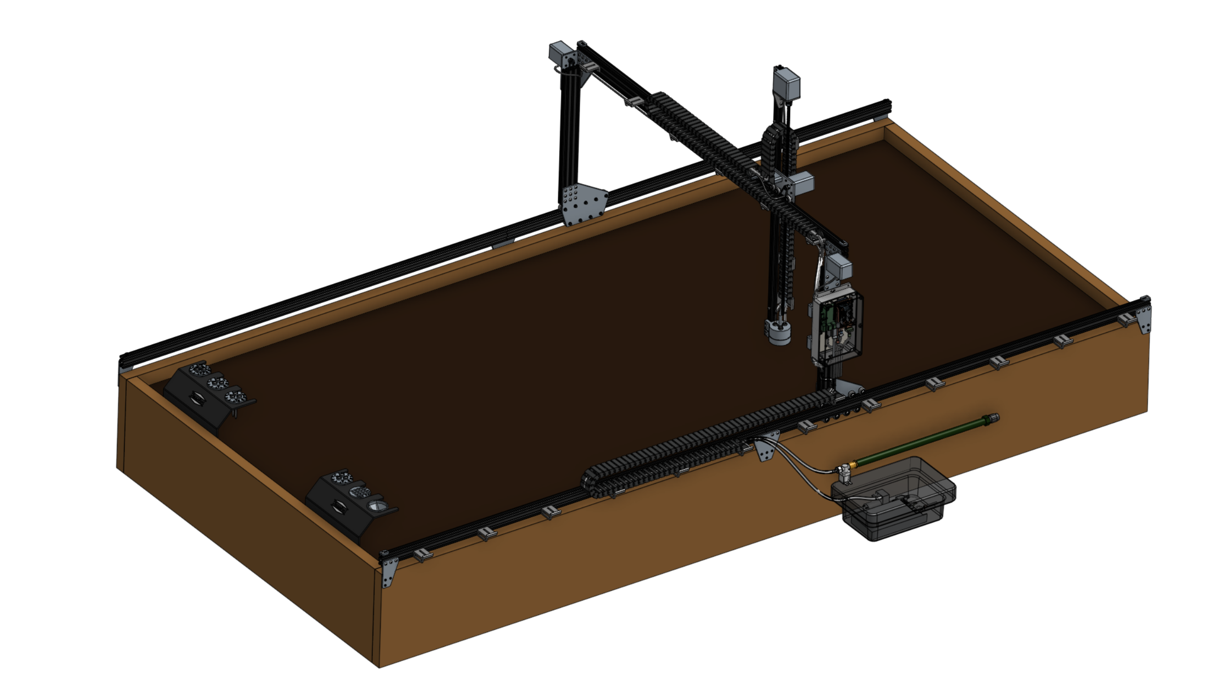
The power supply lives inside the weatherproof SockitBox, along with the vacuum pump.
