Construct the Gantry Structure
Step 1: Attach the plates to the columns
For this part of the assembly you will need:
- The two gantry wheel plate assemblies from the previous page
- The gantry columns (20mm x 60mm x 500mm extrusions)
- 3mm hex driver
Position the gantry column onto the gantry wheel plate assembly. The extrusion should reside on the same side of the plate as the V-wheels and the end of the extrusion should be aligned with the notch in the plate. Tighten the M5 x 10mm screws using a 3mm hex driver.
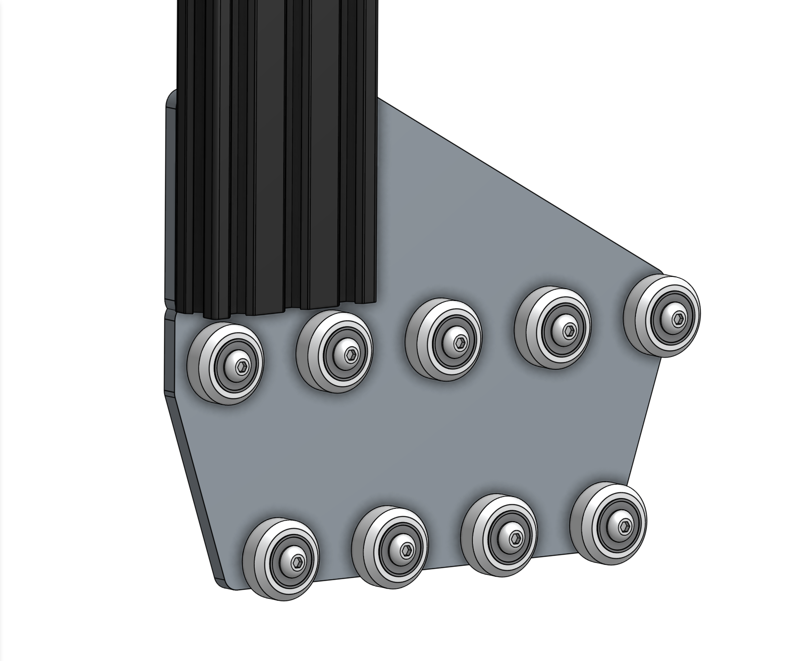
Repeat the above steps for the second gantry wheel plate and aluminum extrusion.
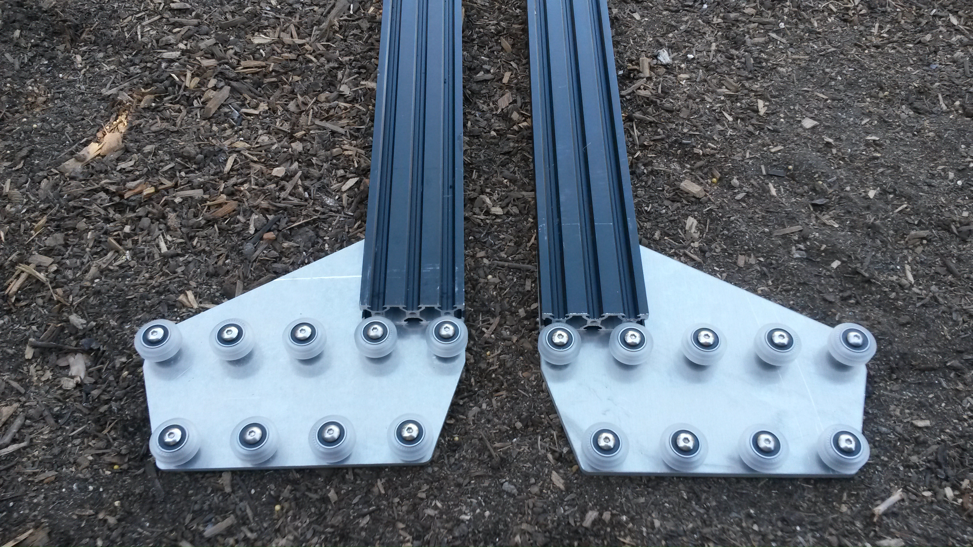
Step 2: Attach the gantry corner brackets
For this step you will need:
- The two gantry wheel plate/column assemblies completed in the previous step
- Two gantry corner brackets
- 20 M5 x 10mm screws
- 20 M5 tee nuts
- 3mm hex driver
Lightly screw together 10 M5 x 10mm screws and M5 tee nuts on the left-side gantry corner bracket as shown.
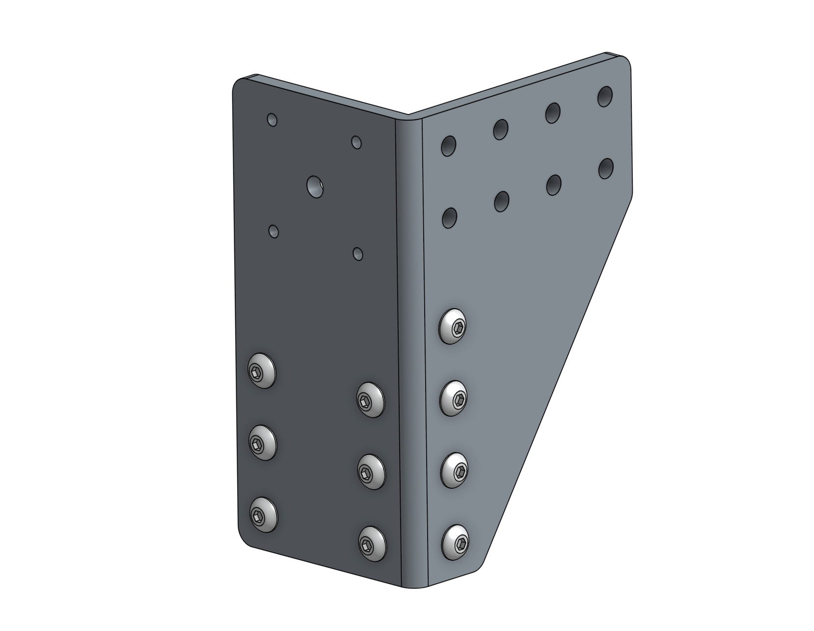
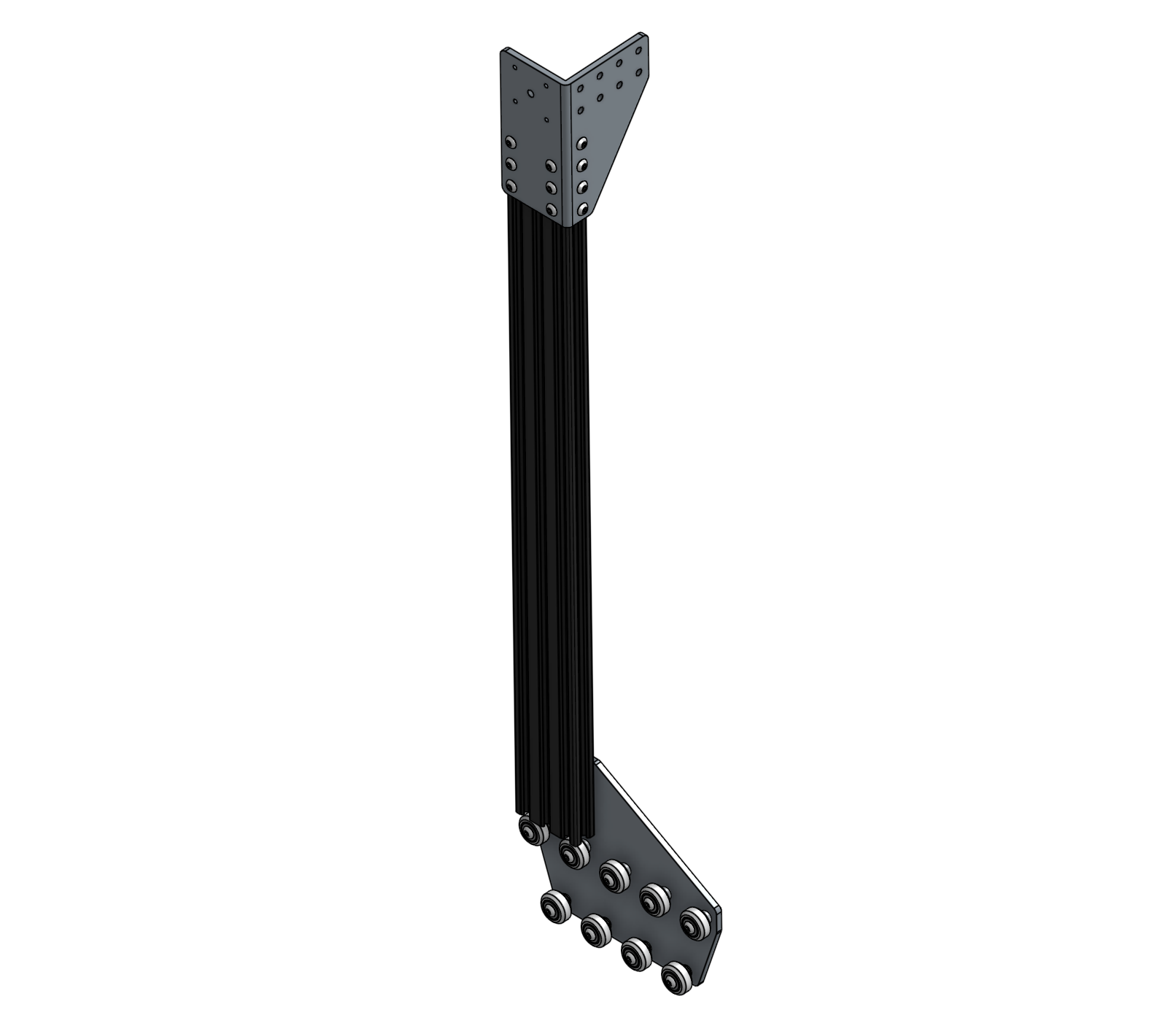
Position the gantry column/plate assembly onto the corner bracket. Pay special attention to the orientation of the bracket, extrusion, and wheel plate. Then tighten the M5 x 10mm screws with the 3mm hex driver.
Step 3: Repeat
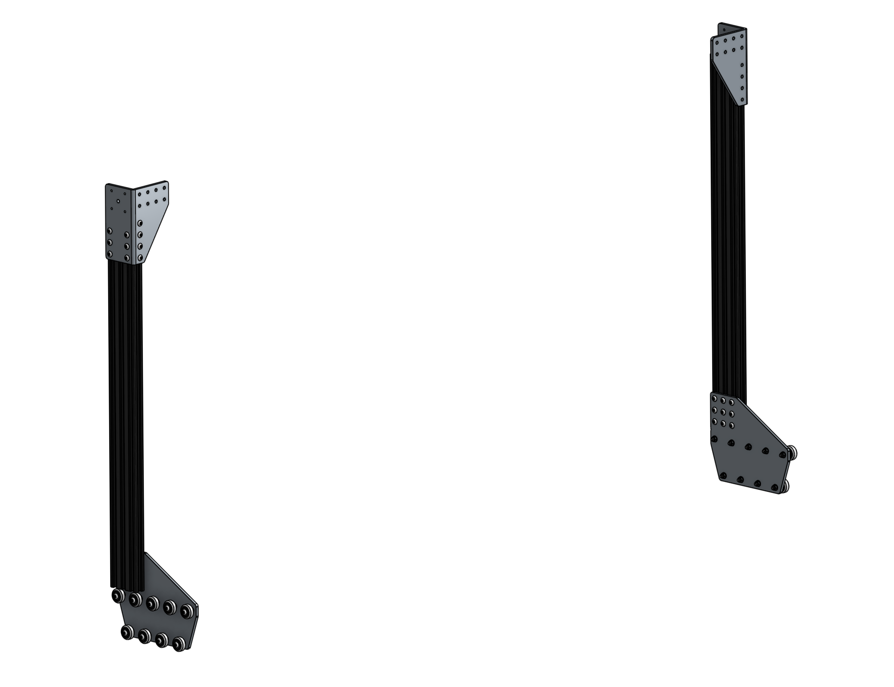
Repeat the above steps for the second corner bracket and column. You should end up with two assemblies that are mirror images of each other. Inspect these images closely to ensure your corner brackets are attached to the columns in the correct orientation.
Step 4: Slide the gantry columns onto the tracks
Adjust the eccentric spacers first
This step is assuming that you have already adjusted the eccentric spacers according to the eccentric spacer adjustment guide.
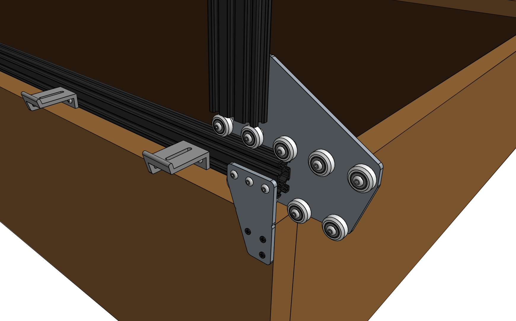
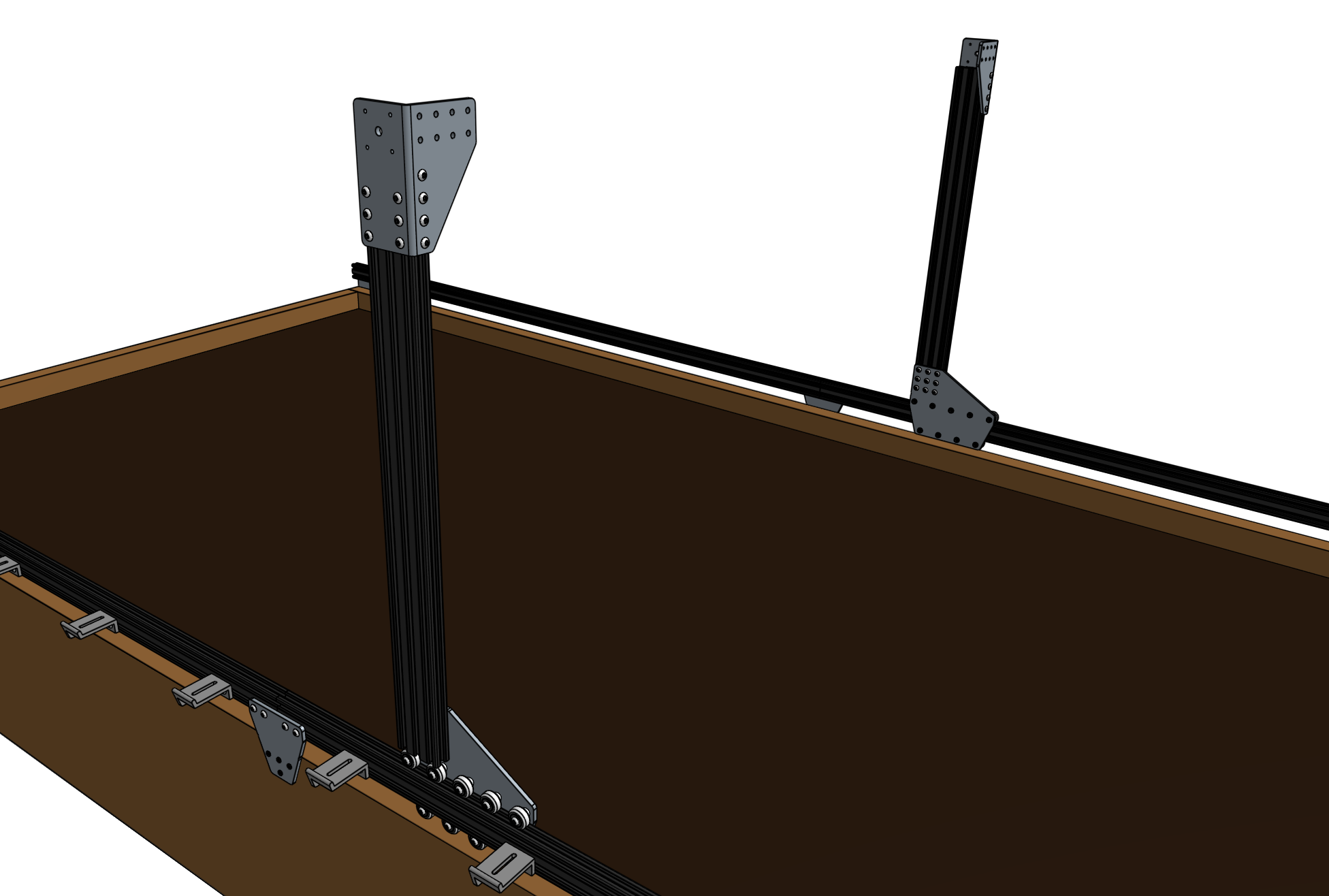
Slide the gantry columns onto the tracks.

Step 5: Attach the main beam
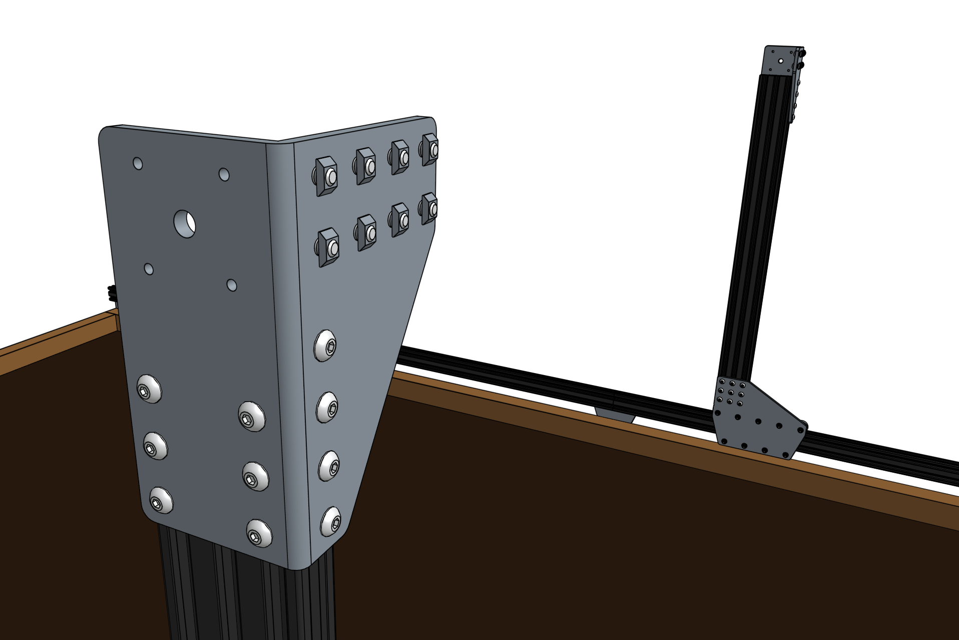
Insert eight M5 x 10mm screws and M5 tee nuts into the front face of each of the gantry corner brackets. The tee nuts should be facing the front of FarmBot.
Grab a friend
The next step requires an additional person to complete.
Lift up the gantry main beam and position it onto the front of the gantry corner brackets. The tee nuts should fit into the lower two extrusion slots of the main beam such that the top face of the main beam is 20mm above the top faces of the gantry corner brackets.
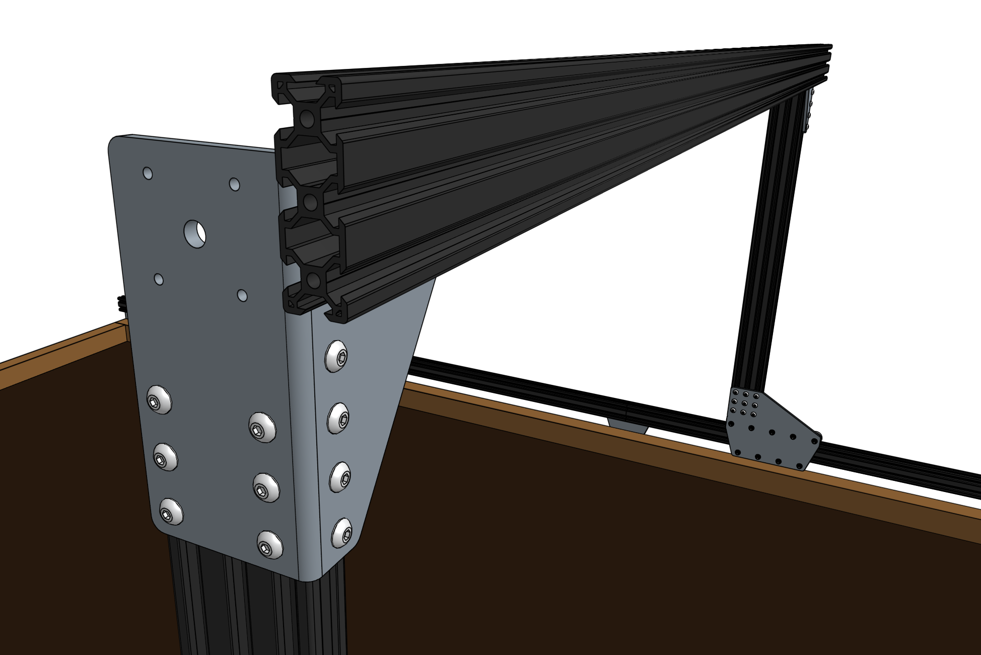

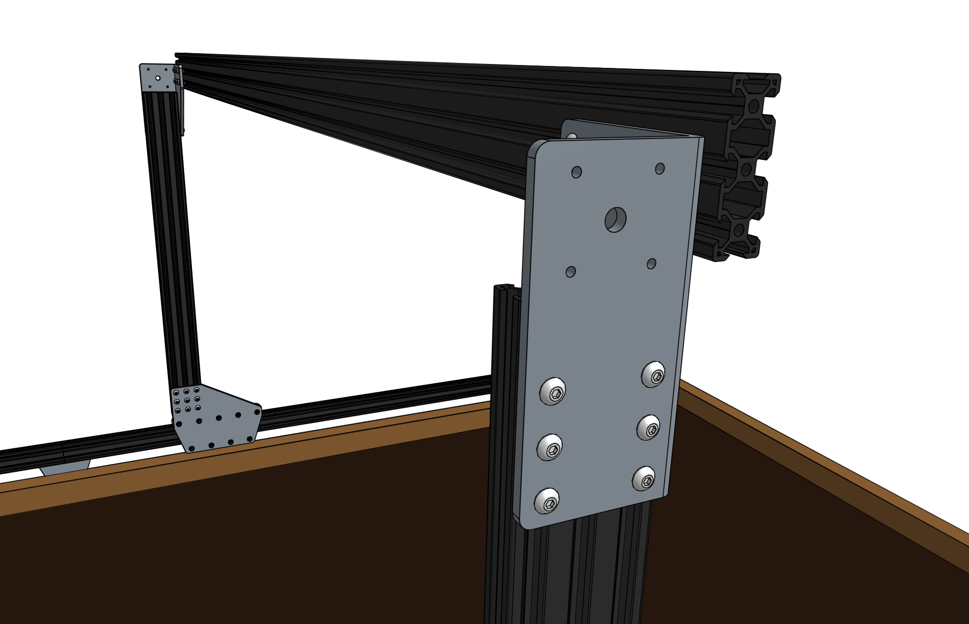
Note that this image is from the backside of FarmBot
Ensure that the gantry columns are vertical and then tighten the 16 M5 x 10mm screws. Depending on the spacing of your tracks, the gantry main beam may extend beyond the corner brackets. This is ok.
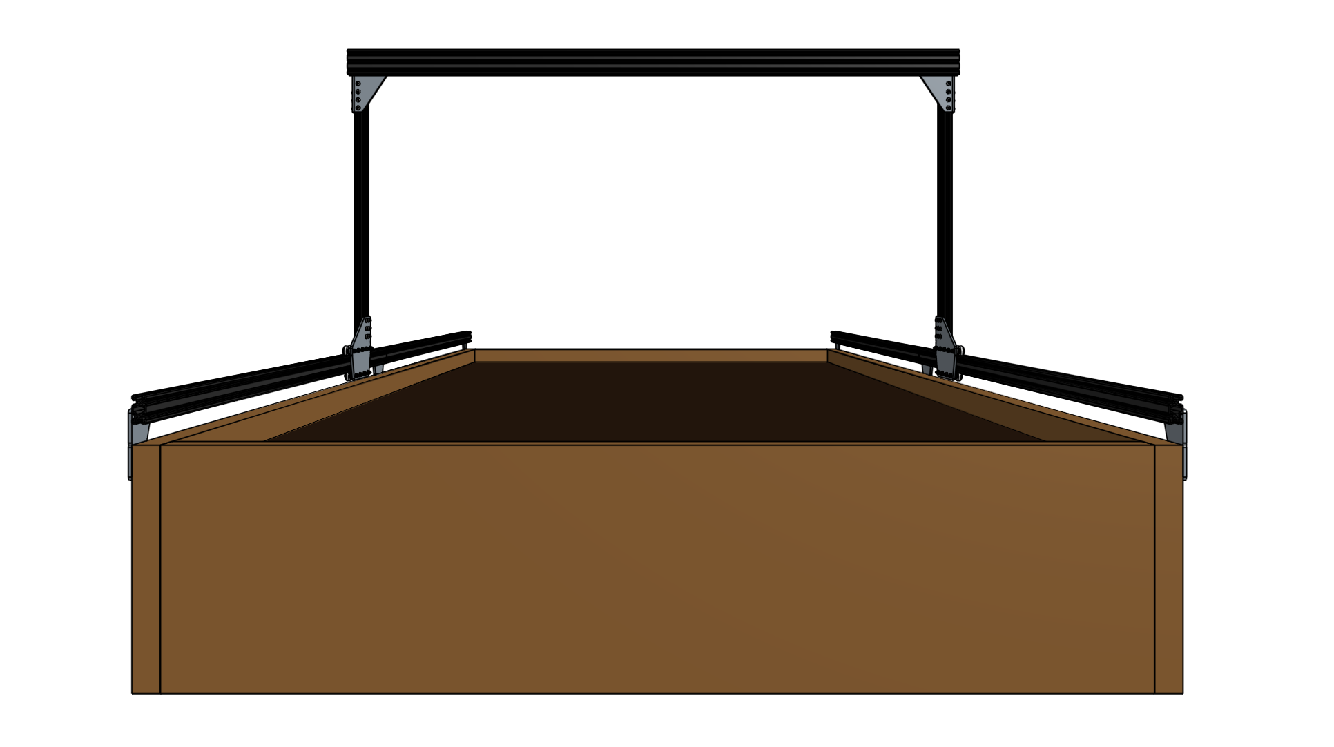

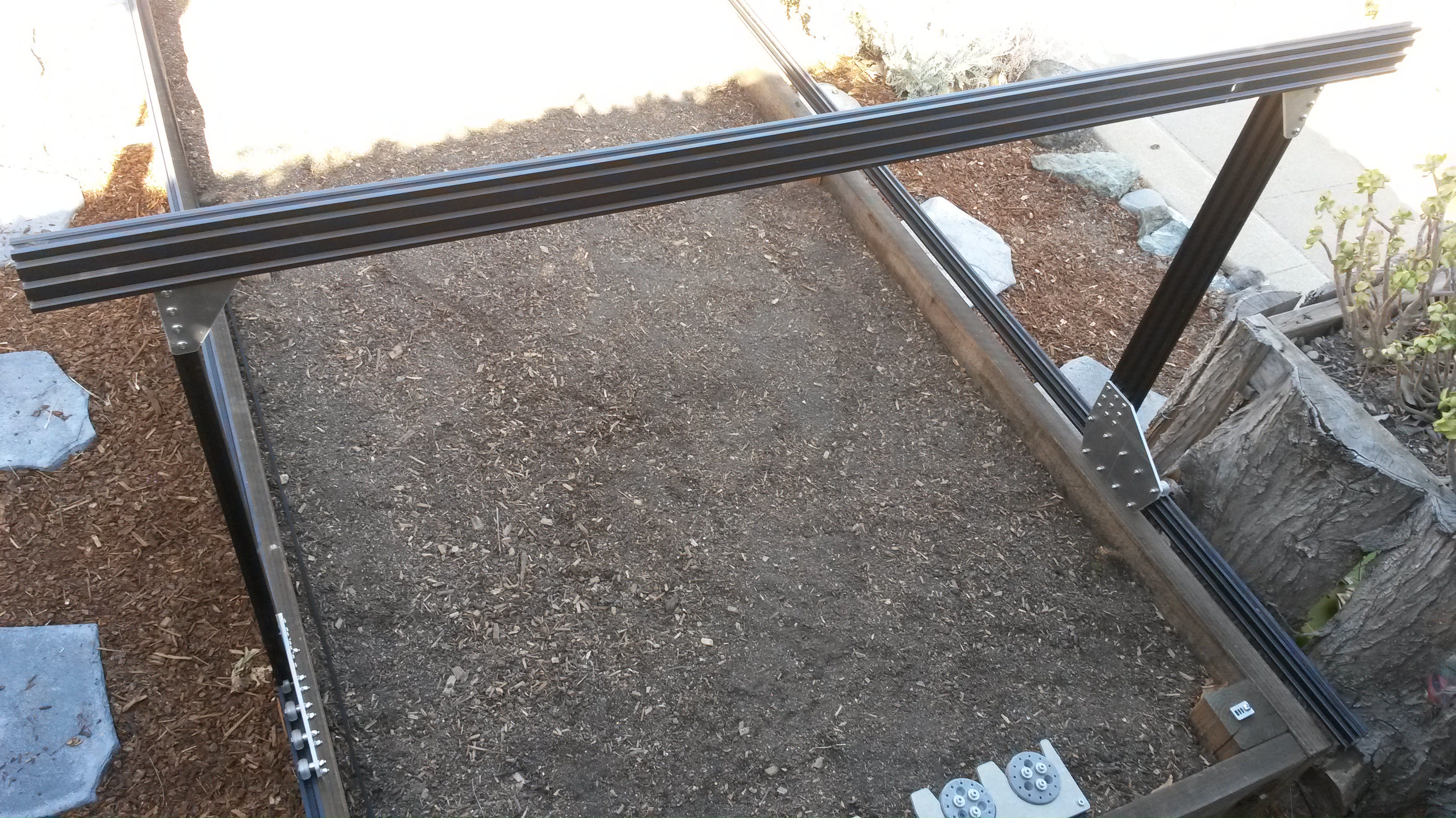
Example gantry where the main beam extends beyond the corner brackets