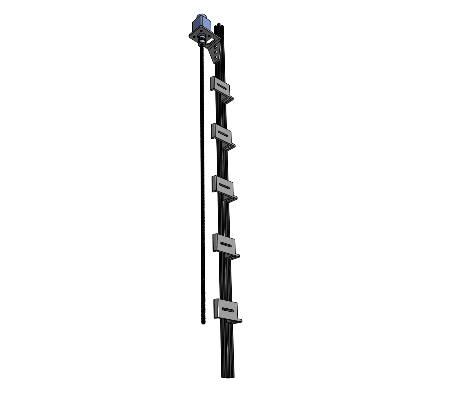
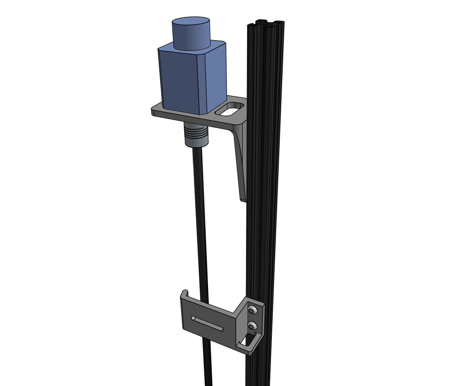
Assemble the Z-Axis
1 hour
This is the estimated time it will take to assemble the z-axis.
Step 1: Attach the stepper motor to the Z-axis motor mount
Attach the stepper motor to the z-axis motor mount using four M3 x 10mm screws. The motor and encoder’s connectors should be facing the back flange of the mount.
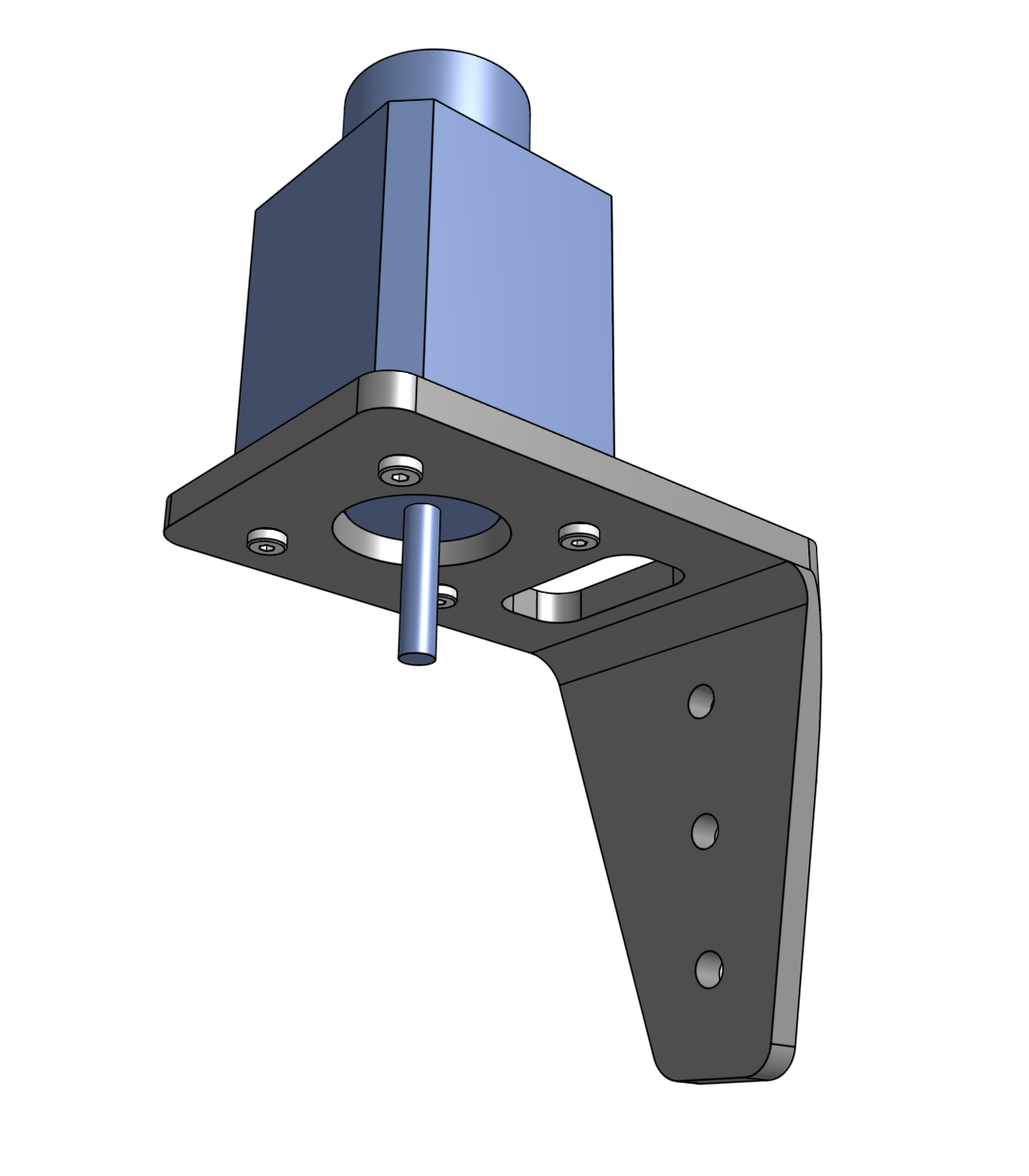
Step 2: Attach the motor mount to the Z-axis extrusion
Partially screw three M5 x 10mm screws and M5 tee nuts into the z-axis motor mount. Position the motor mount onto the z-axis extrusion as shown and tighten. Note that you will need to adjust the position of the motor mount once the cables have been connected and it is time to put the vertical motor housing on.
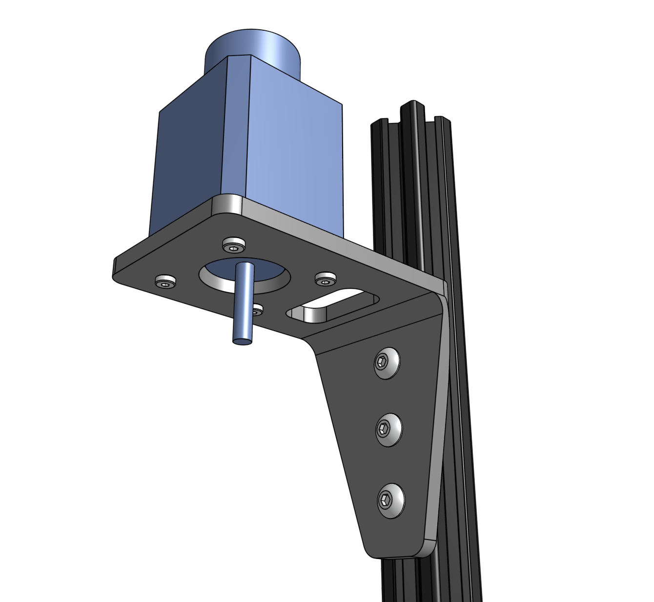
Step 3: Attach the flex coupling
Slide the 5 to 8mm flex coupling onto the motor shaft and tighten the two setscrews. Ensure that the setscrews are positioned onto the flat parts of the motor shaft.
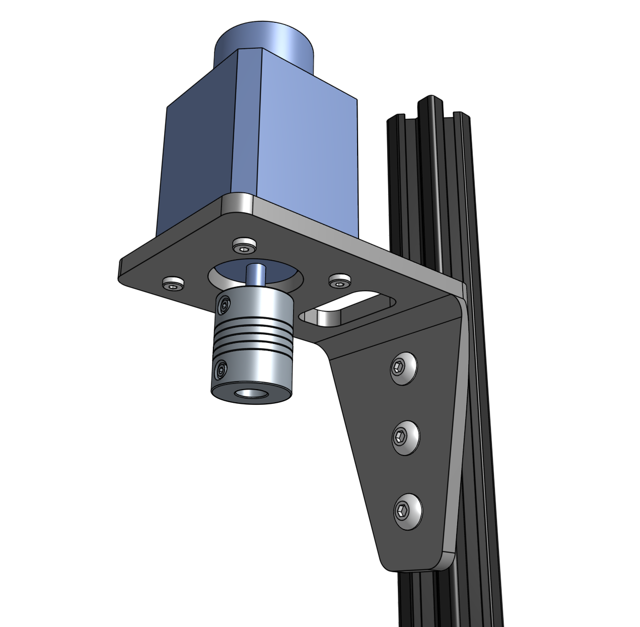
Step 4: Attach the leadscrew
Slide the leadscrew into the flex coupling and tighten the two setscrews.
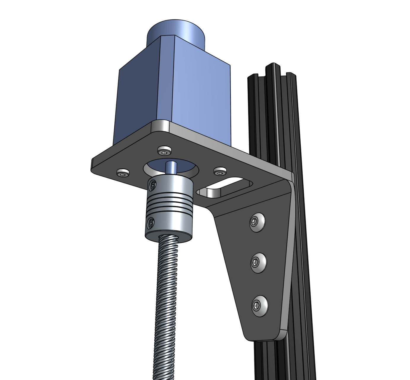
Handle assembly carefully
At this point, the leadscrew is only connected to the rest of the z-axis assembly with the flex coupling. Take care to support the leadscrew when moving the assembly around (before it is fully supported by inserting it into the cross slide assembly) to avoid damaging the flex coupling.
Step 5: Attach the vertical cable carrier supports
Use two M5 x 10mm screws and M5 tee nuts to attach each of the five vertical cable carrier supports to the z-axis extrusion. Space the supports evenly along the extrusion as shown.
