Assemble the Electronics Box
- Step 1: Gather the parts and tools
- Step 2: Install FarmBot OS
- Step 3: Mount the Arduino
- Step 4: Mount the Raspberry Pi
- Step 5: Connect the Arduino to the Raspberry Pi
- Step 6: Mount the plate in the housing
- Step 7: Add the RAMPS shield
- Step 8: Add the stepper drivers
- Step 9: Connect the RAMPS power cable
- Step 10: Connect the Raspberry Pi power cable
- What’s next?
1.5 hours
This is the estimated time it will take to setup the Electronics.
Step 1: Gather the parts and tools
Gather all the parts from the table below and lay them out in a logical manner. To complete the assembly, you will also need the following tools:
Step 2: Install FarmBot OS
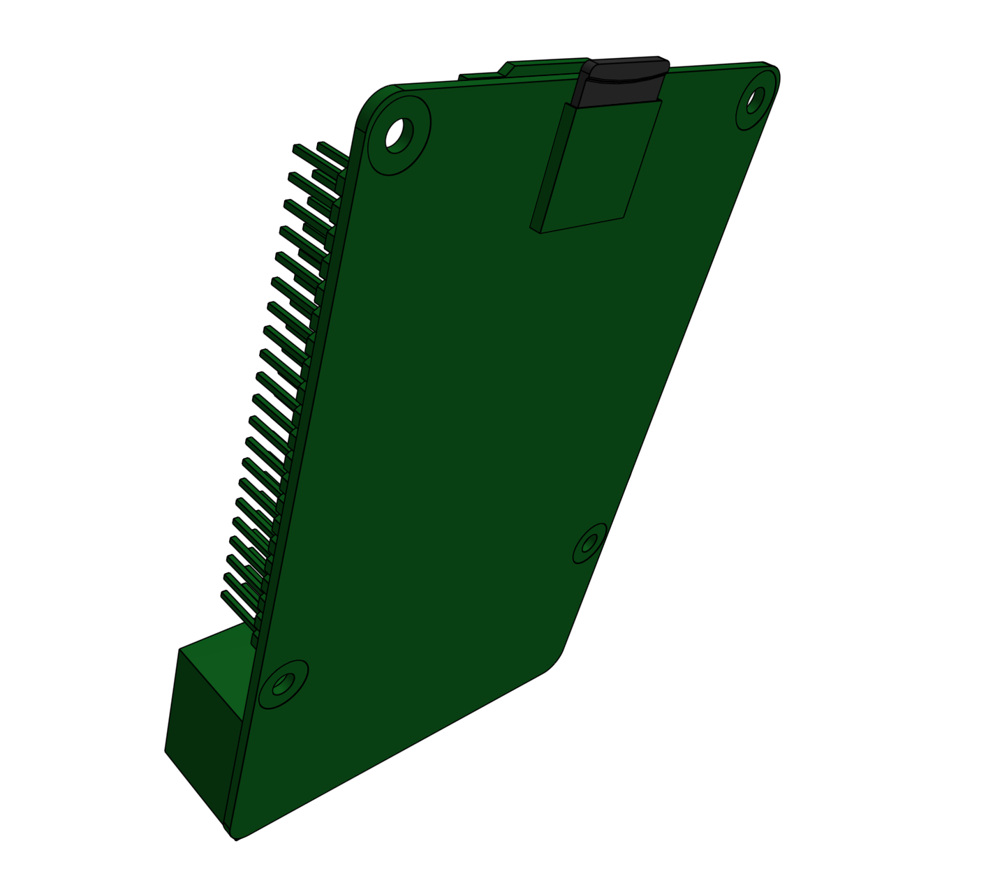
Follow the instructions on the Raspberry Pi software page to install FarmBot OS onto the microSD card. Then insert the microSD card into the slot in the backside of the Raspberry Pi.
Step 3: Mount the Arduino
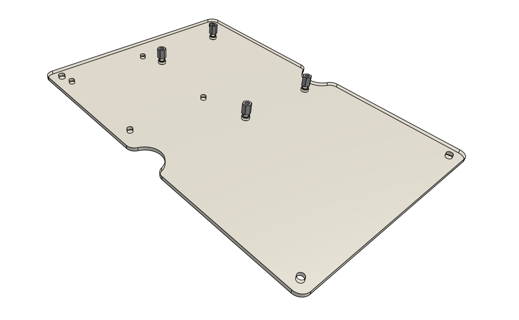
Use four M2.5 x 4mm screws to attach four M2.5 x 6mm standoffs to the electronics mounting plate. The screws should be on the backside of the plate while the standoffs should be on the front.
The electronics mounting plate shipped with the Genesis kits come with a protective cover. Gently peel it off to expose the clear plastic underneath, if desired.
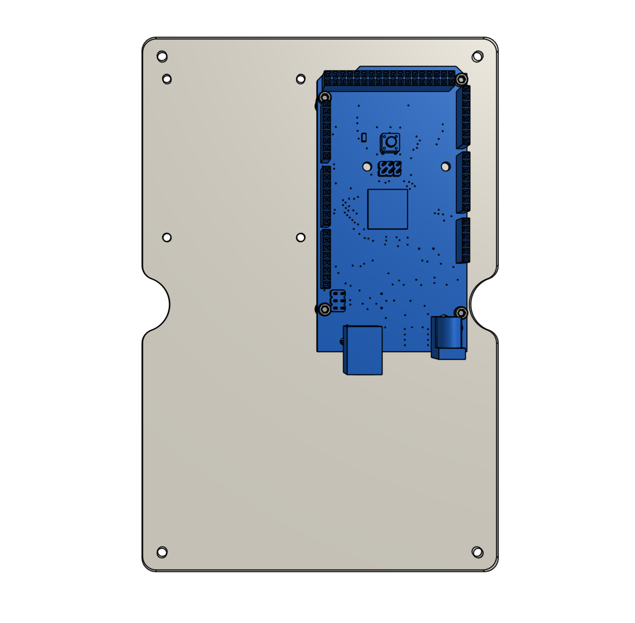
Attach the Arduino to the standoffs using four M2.5 x 4mm screws.
Step 4: Mount the Raspberry Pi
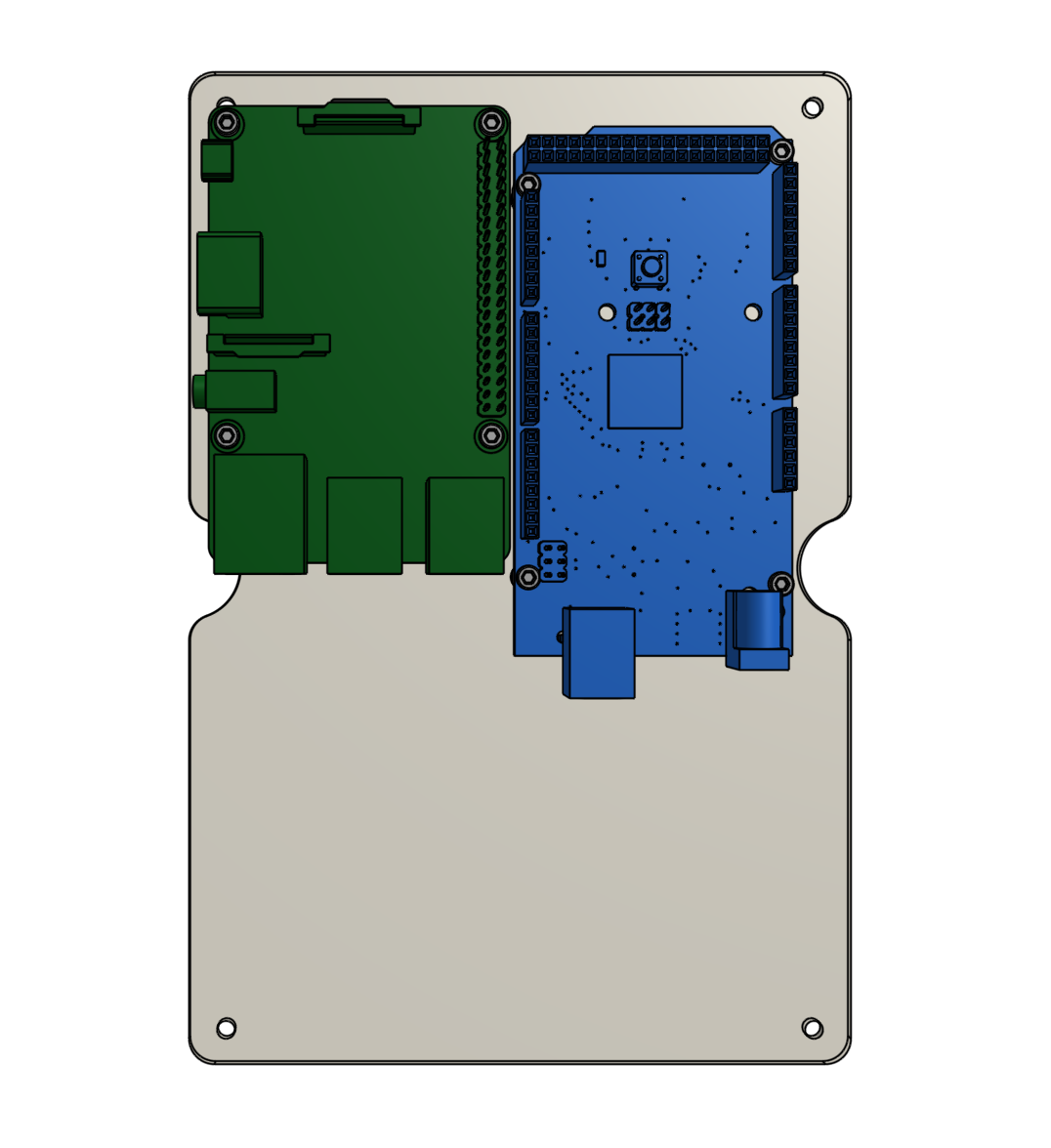
Use four M2.5 x 4mm screws to attach four M2.5 x 16mm standoffs to the electronics mounting plate. The standoffs should be on the same side of the plate as the Arduino.
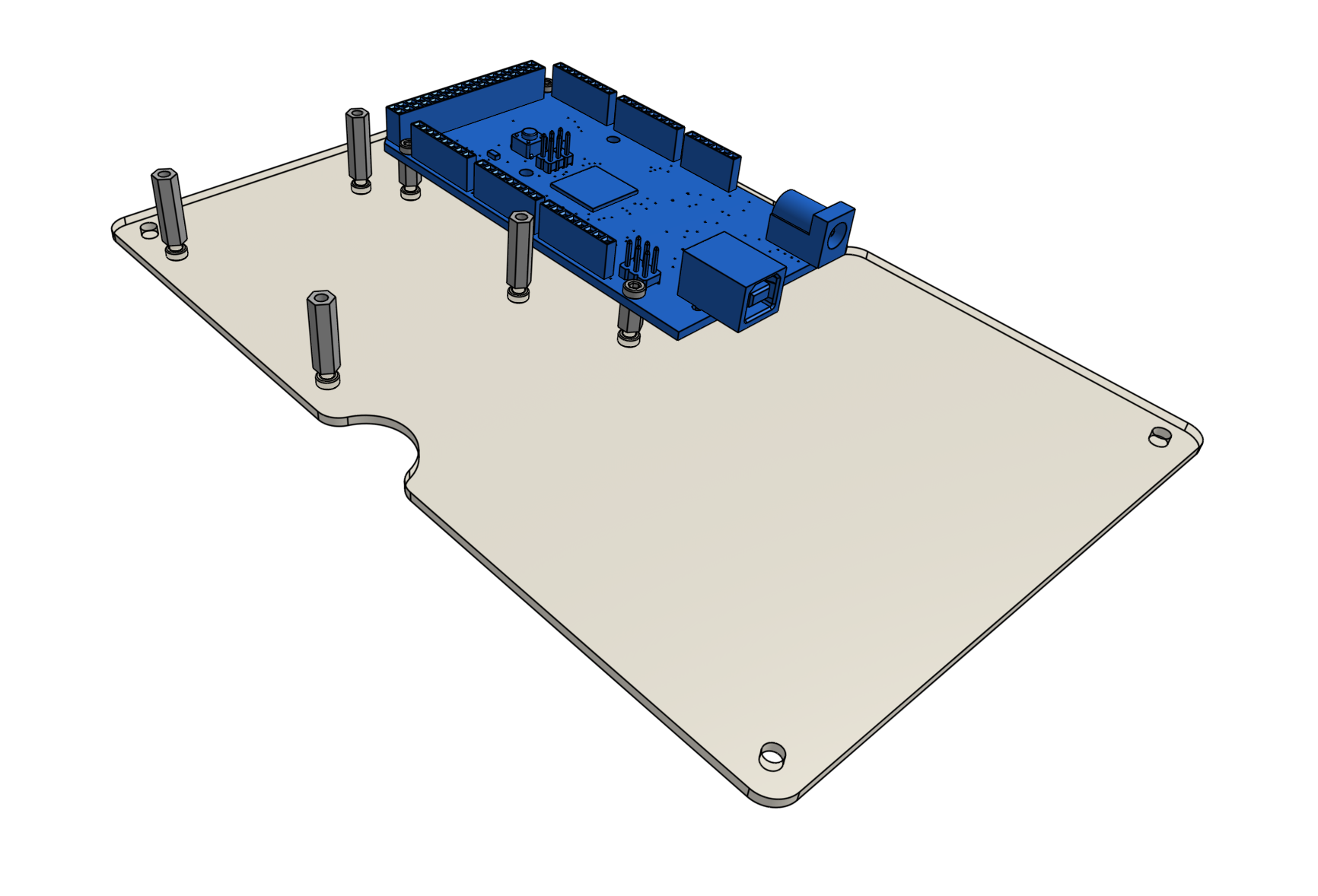
Attach the Raspberry Pi to the standoffs using four M2.5 x 4mm screws.
Step 5: Connect the Arduino to the Raspberry Pi
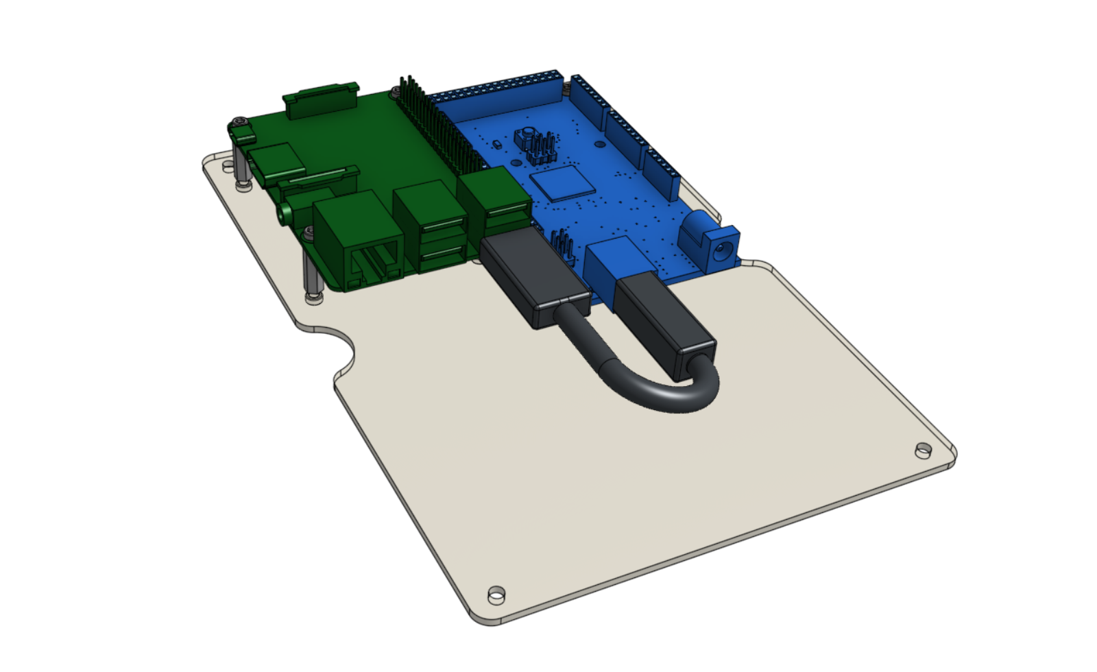
Connect the Arduino to the Raspberry Pi with the USB cable. It does not matter which USB port you plug into on the Pi. If using a short cable, the lower right port is recommended.
Step 6: Mount the plate in the housing
Attach the electronics mounting plate to the electronics housing using four M3 x 5mm screws.
Step 7: Add the RAMPS shield
Align the RAMPS shield on top of the Arduino. The green connectors of the RAMPS shield should be on the same end of the board as the USB port of the Arduino.
Carefully press the two boards together.
Take your time
Make sure that you do not bend any of the RAMPS board pins, and that all of the pins are being inserted into the corresponding black pin headers on the Arduino.
Press firmly.
Step 8: Add the stepper drivers
Stepper drivers are the small circuit boards that mount on top of the RAMPS shield and provide power to the stepper motors. The RAMPS shield has space for up to five drivers, but we’re only going to use four for FarmBot. We’ll use the spaces marked X, Y, Z, and E0.
Expose the adhesive on the bottom of the stepper driver heatsinks.
Attach the heatsink to the black chip on the stepper driver.
Mount the four stepper drivers on top of the RAMPS shield, being careful not to bend any of the pins.
Orientation is important!
The tuning screw on each stepper driver should be on the FAR end of the driver from the green power connectors of the RAMPS shield. If you put your stepper drivers in backwards then you risk frying all of your electronics. Inspect the following photos closely to ensure you insert the drivers correctly.
Better safe than sorry
We cannot stress this enough: If your stepper drivers are incorrectly installed then you risk frying all of your electronics. Double check the photo above one more time to ensure you have mounted your drivers correctly.
Step 9: Connect the RAMPS power cable
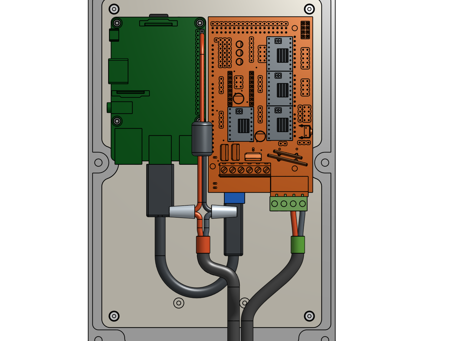
Use the bladed screwdriver to open the two screw terminals on the right side of the green power connector of the RAMPS shield. Then insert the RAMPS power cable’s wires and tighten. The black wire (negative) should be in the right-most terminal.
Note that the green power connector can be removed from the RAMPS shield to ease the installation of the power wires. If you remove the connector, make sure to plug it back in after you connect the wires.
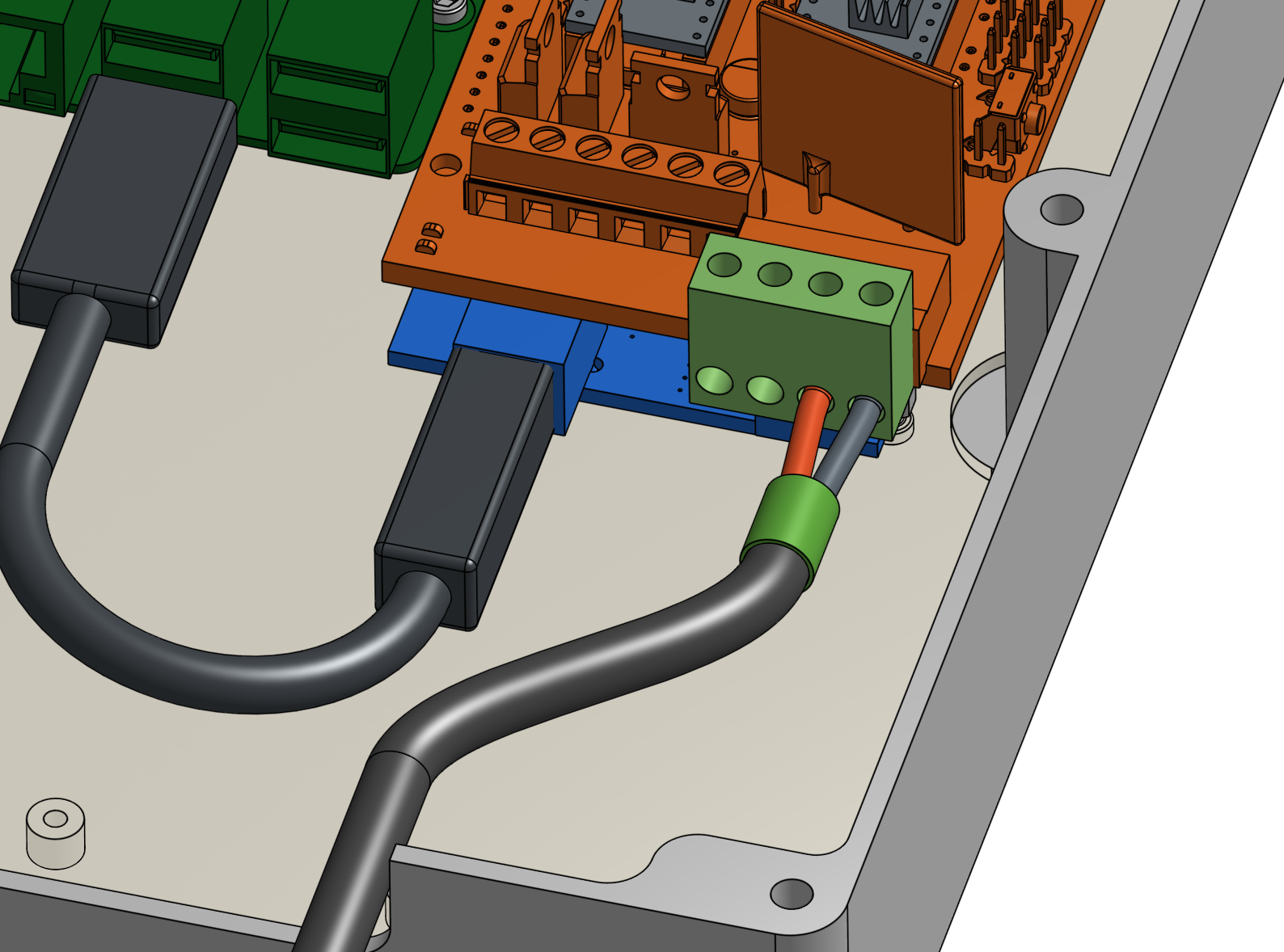
Note that we included an extra RAMPS power cable that you can optionally connect between the power supply and the remaining two ports on the green power connector. You will need to use this if you want to use the high power D8 outputs for an additional peripheral such as LED lights.
Step 10: Connect the Raspberry Pi power cable
Plug the buck adapter into the top right three GPIO pins of the Raspberry Pi. The empty header of the buck adapter should be “connected” to the upper right GPIO pin.
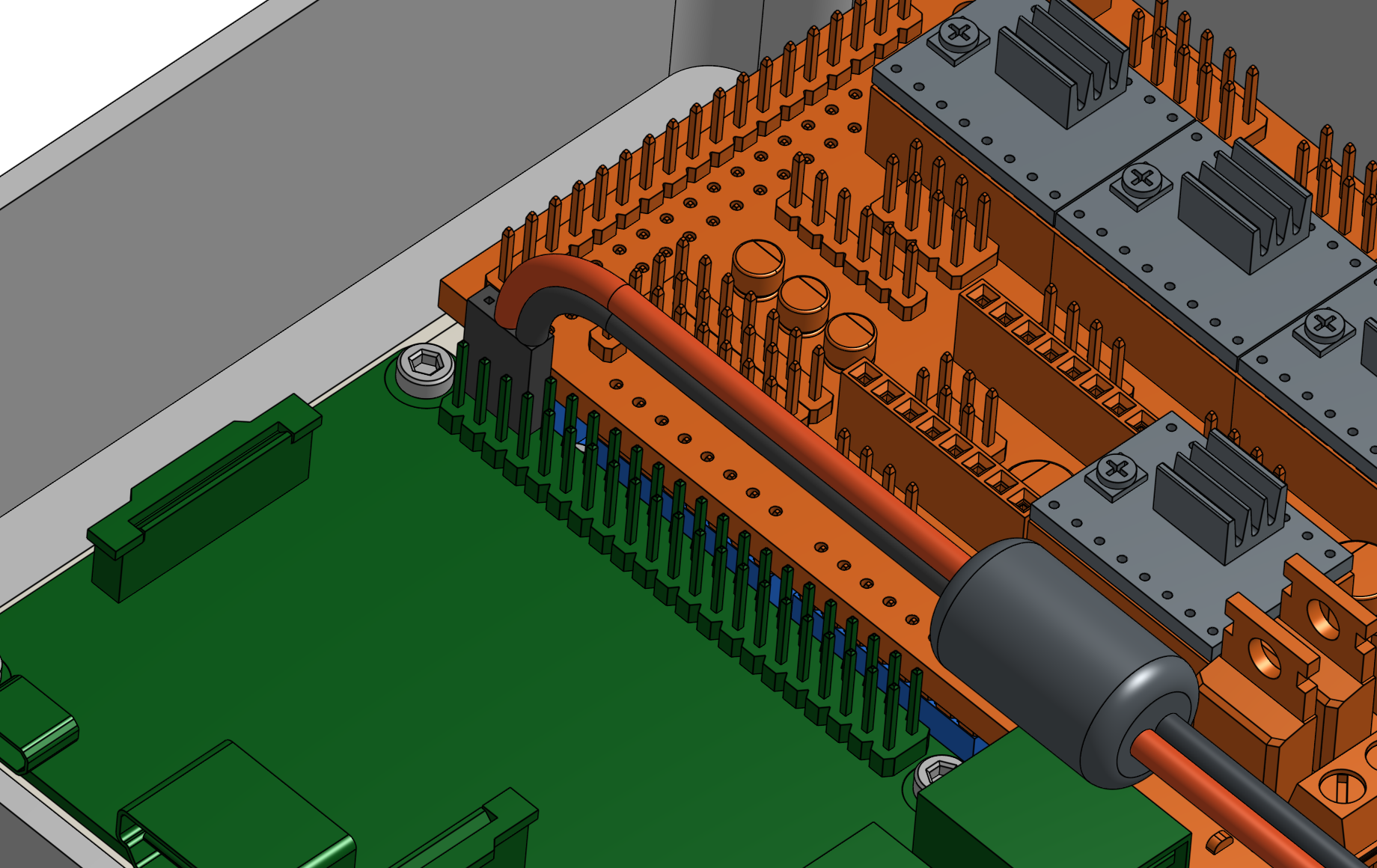

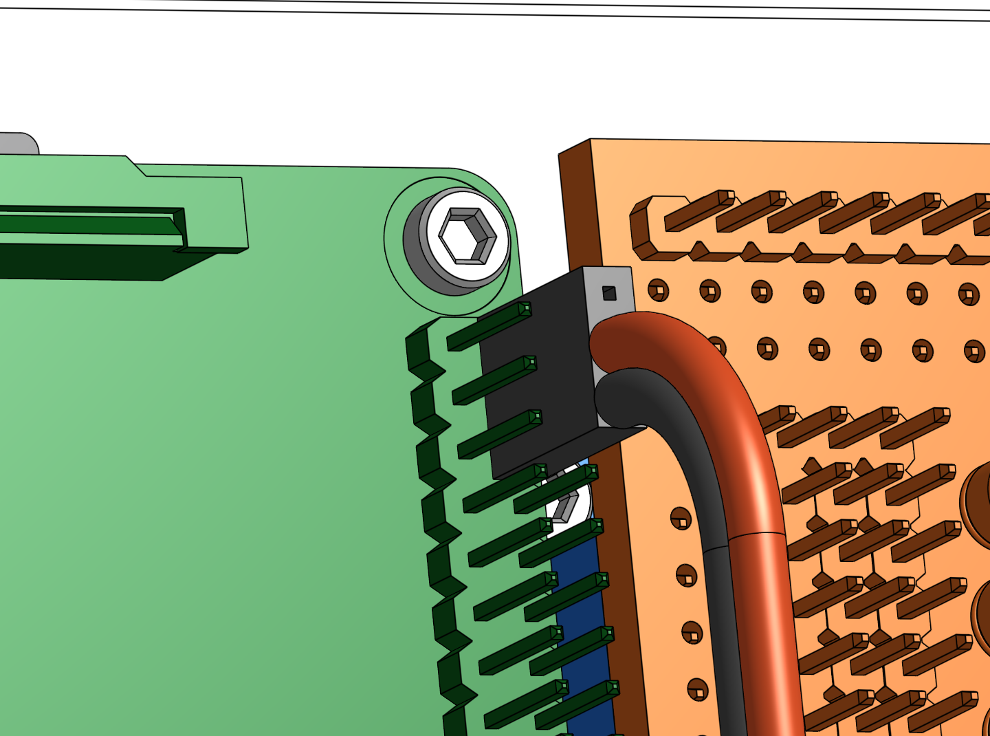
Twist together the free red wire from the buck adapter with the red wire from the Raspberry Pi power cable. Then screw on a wire nut. Repeat for the black wires.
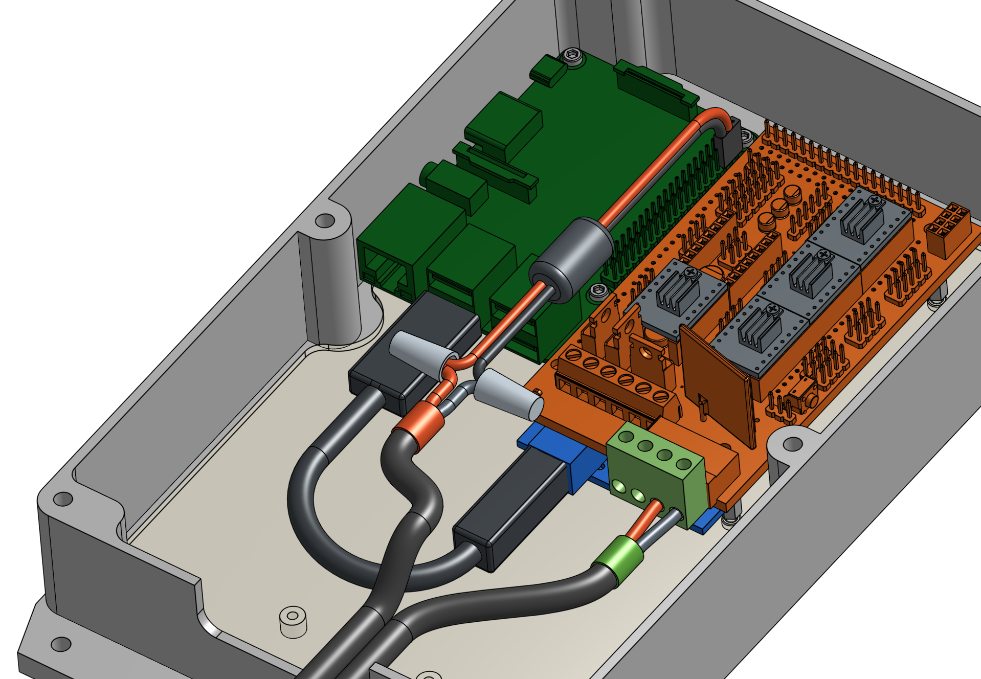

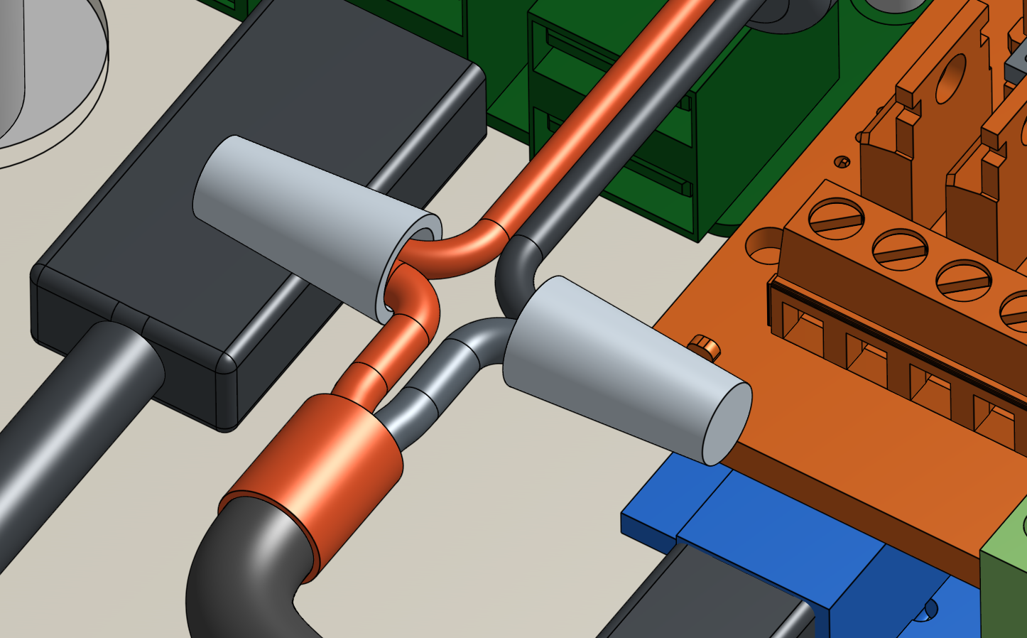
Double check your wiring
It can be easy to accidentally connect wires incorrectly or insert something in the wrong orientation. Because electronics are less forgiving to mistakes, take your time to double check that everything looks right. If so, proceed to the next step!
