Soil Sensor
Documentation and assembly instructions for the FarmBot Genesis soil sensor
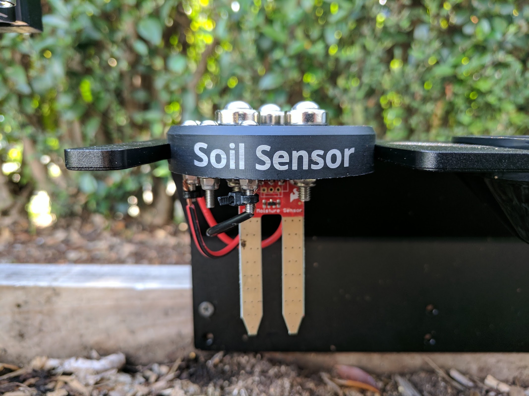
This single 3D printable component magnetically mounts onto FarmBot’s UTM like any other tool. It works by driving the tool vertically into the soil so that the soil properties can be accurately read.

20 minutes
This is the estimated time it will take to assemble the soil sensor.
Step 1: Gather the parts and tools
Gather all the soil sensor parts from the table below and lay them out in a logical manner. To complete the assembly, you will also need the following tools:
| Qty. | Component |
|---|---|
| 1 | Soil Sensor |
| 1 | Moisture Sensor PCB |
| 3 | Ring Magnets |
| 3 | M5 x 30mm Screws |
| 3 | M5 Washers |
| 3 | M5 Locknuts |
| 2 | M3 x 12mm Screws |
| 4 | M3 x 25mm Screws |
| 6 | M3 Locknuts |
| 1 | Jumper Link |
| 4 | Zipties |
Step 2: Install the moisture sensor
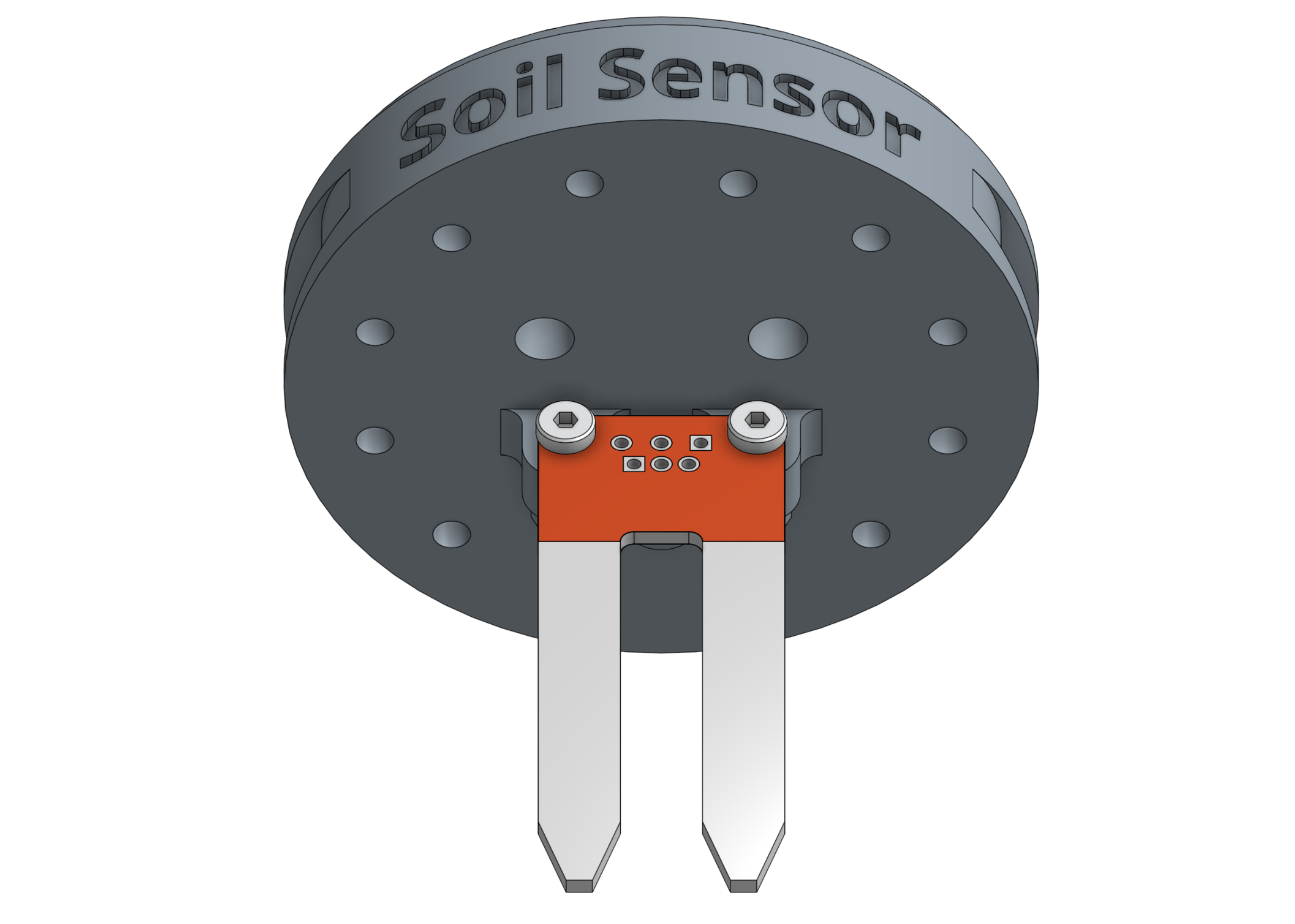
Attach the moisture sensor to the soil sensor base using two M3 x 12mm screws and M3 locknuts. The sensor should be on the front side of the base’s mounting tabs. The heads of the screws should be on the sensor (front) side while the locknuts should be on the mounting tabs (back) side. Do not overtighten the screws as this could damage the soil sensor circuit board.

Step 3: Install the universal tool hardware
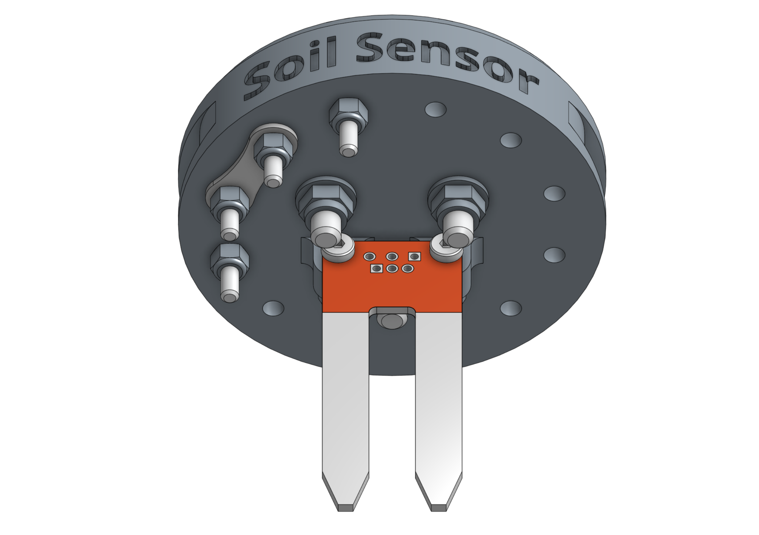
Install the magnets and tool verification jumper link using the instructions in the universal tool hardware reference guide.
Step 4: Install the additional electronic screws
Use the 2mm hex driver and 5.5mm wrench to attach two M3 x 25mm screws and M3 locknuts into the holes labelled A and D on the soil sensor base. The screw heads should be on the same side of the base as the magnets.

Step 5: Wire it up
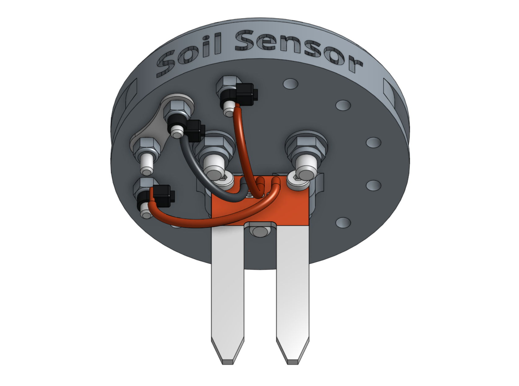
Use zip ties to secure the bare ends of the wires from the moisture sensor to the corresponding electronic screws. The black wire (ground) should be connected to B. The red (signal) wire should be connected to D. And the red (5V) wire should be connected to A.

Note
As of the v4.0.0 software released on June 21, 2017, the UTM Pin/Wire A/1 should be connected to +5V on Arduino/RAMPS, while B/2 should be connected to Ground. This change is because the tool verification pin now uses the pull-up resistor in the firmware, so it should be jumped to Ground, instead of +5V.