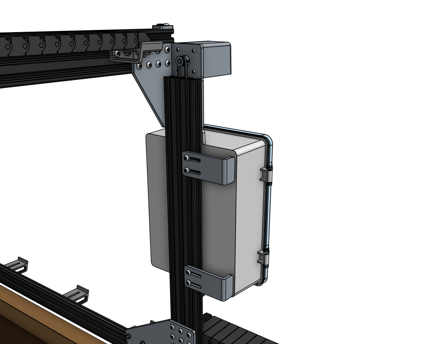
Attach the Electronics Box
Step 1: Gather the parts and tools
Gather all the parts from the table below and lay them out in a logical manner. To complete the assembly, you will also need the following tools:
| Qty. | Component |
|---|---|
| 1 | Electronics Box |
| 6 | M5 x 10mm Screws |
| 6 | M5 Tee Nuts |
| 2 | Cable Guides |
Step 2: Attach the electronics box to the gantry
Attach the electronics box to the middle slot on the outside of the left gantry column using two M5 x 10mm screws and tee nuts. The screws should be placed in the middle holes on the top and bottom mounting flanges of the electronics box. The top flange of the box should be butted against the bottom edge of the gantry corner bracket.

Step 3: Attach the cable guides
Attach both cable guides to the back side of the left gantry column using M5 x 10mm screws and tee nuts as shown. Adjust the guides so they secure the motor and encoder cables, UTM cable, LED lights cable, vacuum pump cable, camera cable, and the water tube. Ensure the water tube is not compressed.

Note: the cables and tubing are not shown in this image.