Soil Sensor
Pre-assembly and packing instructions for the soil sensor
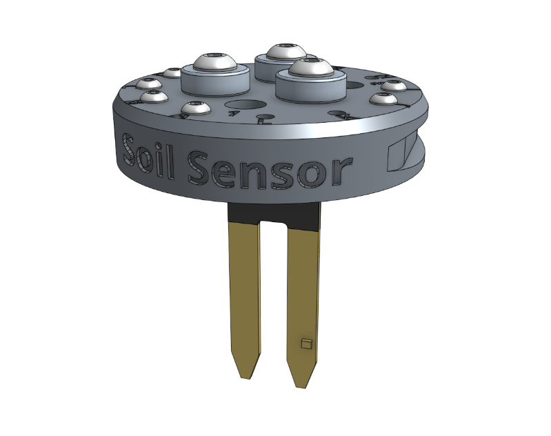
Component list
| Component | Qty |
|---|---|
| Soil Sensor | 1 |
| Soil Sensor PCB | 1 |
| Magnets | 3 |
| M5 x 16mm Screws | 3 |
| M5 Flange Locknuts | 3 |
| M3 x 12mm Screws | 8 |
| M3 Locknuts | 8 |
| Jumper Link | 1 |
| Soil Sensor Box | 1 |
| Soil Sensor Box Insert | 1 |
Step 1: Install the magnets
Install only the magnets using the instructions in the basic tool hardware reference guide.
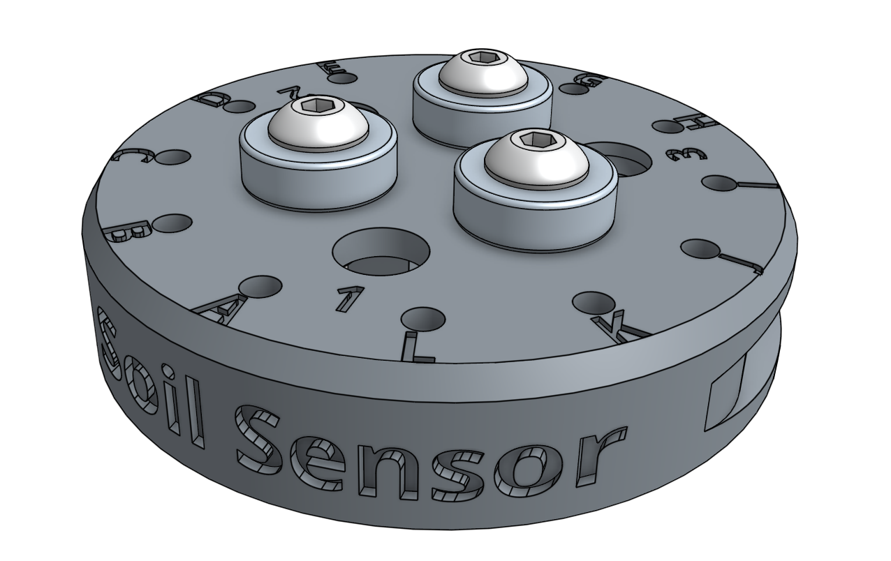
Step 2: Install the soil sensor PCB
Attach the soil sensor PCB to the soil sensor using two M3 x 12mm screws and M3 locknuts. The sensor should be on the front side of the base’s mounting tabs. The heads of the screws should be on the PCB’s front side while the locknuts should be on the mounting tabs’ back side. Do not over tighten the screws as this could damage the circuit board.
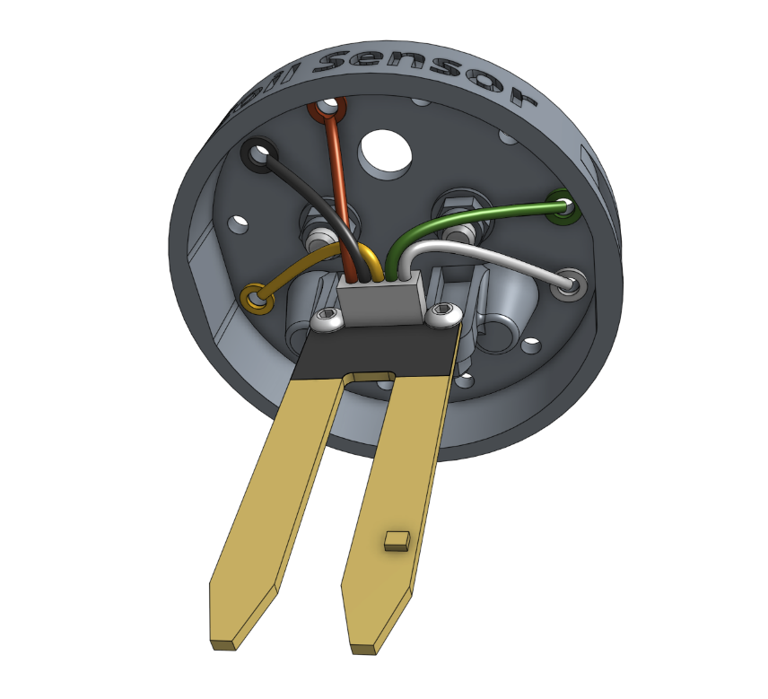
Step 3: Install the electronic screws
Use the 2mm hex driver and 5.5mm box wrench to secure the following ring terminals to the soil sensor with M3 x 12mm screws and M3 locknuts. The screw heads should be on the same side as the magnets.
| Soil Sensor Position | Wire Color | Connected to |
|---|---|---|
| A | red | VCC |
| D | yellow | SIG |
| I | white | SCL |
| J | green | SDA |
Don't jump the gun
The black (GND) wire will be connected differently in the next step.
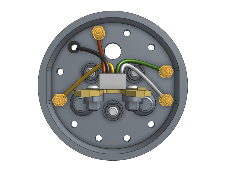
The screws and nuts are highlighted orange
Step 4: Install the jumper link
Attach a jumper link to positions B and C using two M3 x 12mm screws and M3 locknuts. The screw in the B position should hold the ring terminal of the black (GND) wire.
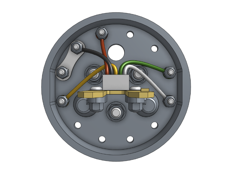
Step 5: Pack
Place the soil sensor box insert into the soil sensor box. Then insert the pre-assembled soil sensor into the box and close the lid.
Box specifications
| Box style | Top flap (standard FarmBot box design) |
| Inner dimensions (L x W x H) | 75mm x 75mm x 90mm |
| Outer dimensions (L x W x H) | 80mm x 80mm x 95mm |
| Material | Cardboard |
| Color | Brown |
| Printing | SOIL SENSOR.pdf |
| Fill | Cardboard insert |